


12 (GB)
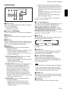
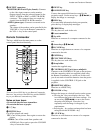
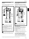
Connector panel
1 INPUT A connectors
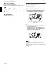
1DIGITAL RGB/5BNC/RGB switch: Selects
DIGITAL RGB, 5BNC or RGB on INPUT A
connectors. Select the appropriate position
depending on the input signal.
DIGITAL RGB: Signal input from DIGITAL
RGB connector.
5BNC: Signal input from the 5BNC connector.
RGB: Signal input from the RGB connector.
2RGB input connector (HD D-sub 15-pin,
female): Connects to the monitor output on a
computer using the supplied cable. This
connector only accepts signals from a computer.
35BNC input connectors (R/R-Y/P
R, G/Y, B/B-
Y/P
B, SYNC/HD, VD connectors) (BNC type):
Connect to a high-resolution computer or VCR
where signals are transmitted long distances; for
example, when the projector has been hung from
the ceiling.
According to the connected equipment, computer,
component (R-Y/Y/B-Y), HDTV or DTV (DTV
GBR, DTV YP
BPR) signal is selected.
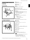
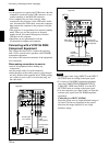
Right side
Location and Function of Controls
4DIGITAL RGB input connector (DFP 20-pin,
TMDS): Connects to a digital RGB output
connector on external equipment.
5USB connector: Connects your computer or
USB equipment.
A plug: (Right, for downstream, 4-pin):
Connects to USB
equipment
.
B plug: (Left, for upstream, 4-pin):
Connects to
a computer. If you connect the projector and a
computer, the projector automatically assumes
that a USB mouse is connected; this allows you
to control the mouse from the Remote
Commander.
6MOUSE (13-pin) connector: Connects to the
mouse port on a computer to control the mouse
function using the supplied mouse cable.
7AUDIO (stereo mini-jack) jack: Connects to the
audio output on a computer.
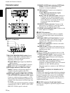
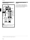
2 INPUT B connectors
Connect to external equipment such as a computer.
You can control the mouse signal with the Remote
Commander.
RGB input (HD D-sub 15-pin, female): Connects
to the monitor output on a computer using the
supplied cable. This connector only accepts
signals from a computer.
AUDIO (stereo mini-jack): Connects to the audio
output on a computer.
MOUSE (13-pin): Connects to the mouse port on a
computer to control the mouse function using the
supplied mouse cable.
3 VIDEO IN jacks
Connect to external video equipment such as a VCR.
S VIDEO (mini DIN 4-pin):
Connects to the S video
output (Y/C video output) on video equipment.
VIDEO (phono type): Connects to the composite
video output.
AUDIO input L (MONO)/R (phono type): Connect
to the audio output of equipment. For stereo
equipment, use both the L and R jacks; for monaural
equipment, use the L (MONO) jack only.
The audio signals are common to the VIDEO and
S VIDEO.
4 CONTROL S IN/PLUG IN POWER (DC 5V
output) jack
Connects to the control S out jacks of the Sony equipment.
Connects to the CONTROL S OUT jack on the supplied
Remote Commander when using it as a wired Remote
Commander. In this case, you do not need to install the
batteries in the Remote Commander, since the power is
supplied from this jack.
5 RS-232C connector (D-sub 9-pin, female)
Connects to a computer to operate the projector from
the computer.
RS-232C
IN
PLUG IN POWER
OUTPUT
INPUT A
INPUT B
VIDEO IN
CONTROL S
REMOTE
DIGITAL RGB
USB
R/R-Y/P
R
B/B-Y/P
B
SYNC/HD VDG/Y
MOUSEAUDIORGB
MOUSEAUDIOAUDIO RGB
MONITOR
S VIDEO VIDEO AUDIO
L
R
(MONO)
DIGITAL
RGB RGB
5BNC
RS-232C
IN
PLUG IN POWER
OUTPUT
INPUT A
INPUT B
VIDEO IN
CONTROL S
REMOTE
DIGITAL RGB
USB
R/R-Y/P
R
B/B-Y/P
B
SYNC/HD VDG/Y
MOUUSEAUDIORGB
MOUUSEAUDIOAUDIO RGB
MONITOR
S VIDEO VIDEO AUDIO
L
R
(MONO)
DIGITAL
RGB RGB
5BNC
34
2
1
6
5
INPUT A
DIGITAL RGB
USB
R/R-Y/P
R
B/B-Y/P
B
SYNC/HD VDG/Y
MOUSEAUDIORGB
DIGITAL
RGB RGB
5BNC
76
2
1
5
3
4