4
Setup
Setup
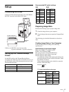
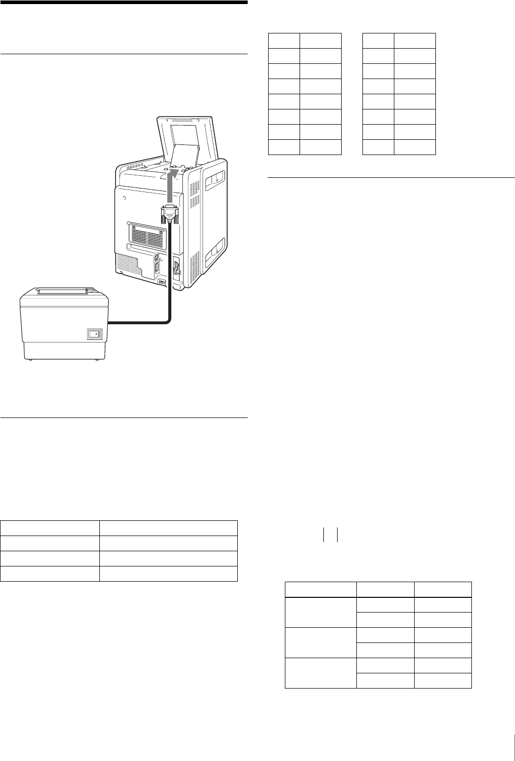
Connecting the Printer
Connect the Thermal Receipt Printer to the UP-CR20L’s
RS-232C connector with an RS-232C cable.
Cable to use: RS-232C cross (reverse) cable
(9-pin D-sub female - 25-pin D-sub male)
Setting Up the Thermal Receipt
Printer
Set the DIP switch on the Thermal Receipt Printer
according to the following chart. For details on how to set
the DIP switch, refer to the operating instructions for the
Thermal Receipt Printer.
Recommended DIP switch settings:
Preparing Image Data
Perform the following steps to prepare image data.
1
Create the image data on your computer.
2
Copy the image data onto an expansion CompactFlash
card.
The following gives detailed information on the above
steps.
Creating Image Data on Your Computer
Create the image data according to the following
specifications.
Specifications for job ticket images
Image size: 360(H) × 2 to 360(V) pixels
Format: 24-bit Windows BMP
File storage location: \Sony\UPCR20\Ticket
Data file name for upper image: Logo.bmp
Data file name for lower image:
A combination of letters and numbers that indicate the
print type and print size are used for file names. Name
the data files as follows.
When creating an image for the initial fee, name the
data file “INIT_FEE.bmp”.
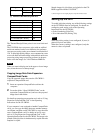
A Letters that indicate print types
Baud rate 38,400 bps
Handshake XON/XOFF protocol
Data length 8 bits
Parity check None
RS-232C
cable
TM-T88 III/TM-T88 IV
Thermal Receipt Printer
Print type Finish Letters
Select & Print Glossy P
ProMatte PM
Index print Glossy I
ProMatte IM
Split image Glossy S
ProMatte SM
SW1
1-1 OFF
1-2 OFF
1-3 ON
1-4 OFF
1-5 OFF
1-6 OFF
1-7 ON
1-8 ON
SW2
2-1 OFF
2-2 OFF
2-3 OFF
2-4 OFF
2-5 OFF
2-6 OFF
2-7 OFF
2-8 OFF
Example: P_3x5.bmp
A B


