


16
VPL-FX30
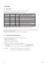
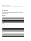
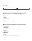
D4 D5 D6 D7
(MSB)(LSB) (EVEN) BIT
PARITY STOP
BIT
START D3D2D1D0
3. RS-232C
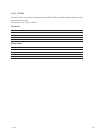
3-1. Connection
Communication is enabled by the use of a D-Sub 9 Pin cross (reverse) cable.
The pin assignment of D-Sub 9 Pin and D-Sub 25 Pin is as follows.
D-Sub 9 Pin D-Sub 25 Pin Name
Shell = FG 1 FG Grounding for safety protection or cable shield
3 2 TxD Transmission data
2 3 RxD Reception data
7 4 RTS Transmission request
8 5 CTS Transmission permission
6 6 DSR Data set ready
5 7 SG GND for signal
1 8 DCD Data channel signal carrier detection
4 20 DTR Data terminal ready
9 22 RI Calling display (Presence/absence of calling signal)
Pin numbers indicated as D-Sub 25 Pin are not used.
Assured cable length: 15 m (However, assurance may not be applicable for some cables.)
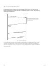
The software for controlling the projector from a PC is intended for performing transmission and recep-
tion for only the TxD and RxD lines.
Therefore the handshake normally performed by RS-232C is not necessary.
3-2. Communication Specifi cations
. Full duplex communication channels (Flow control not performed.)
. Start-stop synchronism system
. Baud rate: 38.4 kbps (bits per second)
. The bit confi guration is defi ned as follows.
1 START Bit + 8 DATA Bits + 1 PARITY Bit + 1 STOP Bit
EVEN Parity ...........Total number of “1”s from D0 to D7 is an even number. 8 0
...........Total number of “1”s from D0 to D7 is an odd number. 8 1