


54
D
D
E
F
1
2
3
4
5
6
7
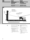
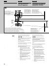
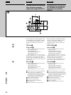
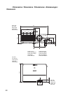
For more details on the ceiling installation, refer
to the Installation manual for Dealers of the PSS-
610. The installation measurements are shown
above when you install the projector on the
ceiling.
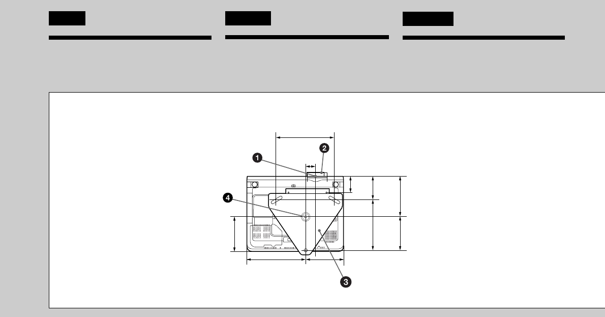
Top view D
Front view E
b) Distance between the ceiling and the surface
of the mounting bracket
Using adjustment pipe (b):
150/175/200 mm (6/7/7
7
/8 inches)
Using adjustment pipe (c):
250/275/300 mm (9
7
/8 /10
7
/8 /11
7
/8 inches)
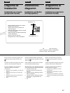
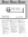
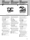
The lens is offset 43 mm (1
3
/4 inches) to the right
from the center of the supporting pole. When
mounting, take care to align the center of the lens
with the center of the screen; not the center of the
supporting pole.
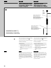
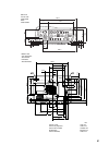
Side view F
b) Distance between the ceiling and the surface
of the mounting bracket
Using adjustment pipe (b):
150/175/200 mm (6/7/7
7
/8 inches)
Using adjustment pipe (c):
250/275/300 mm (9
7
/8 /10
7
/8 /11
7
/8 inches)
1 Center of the lens in the horizontal direction
2 Front of the lens (The standard lens is
recessed 4mm inside of the front of the set.
In the ZM102, the lens protrudes 32mm from
the front of the set. In the FM22, the lens
protrudes 6mm from the front of the set.)
3 Upper ceiling mount bracket
4 Center of the supporting pole
5 The surface of the mounting bracket
6 Center of the lens
7 Center of the lens in the vertical direction
Pour plus de détails sur l'installation au plafond,
reportez-vous au manuel d'installation pour les
revendeurs du PSS-610. Les dimensions
d'installation pour le montage au plafond sont
indiquées ci-dessus.
Vue du dessus D
Vue frontal E
b) Distance entre le plafond et la surface du
supprt de montage
Utilisation du tube de réglage (b):
150/175/200 mm (6/7/7
7
/8 pouces)
Utilisation du tube de réglage (c):
250/275/300 mm (9
7
/8 /10
7
/8 /11
7
/8 pouces)
L’objectif est décalé de 43 mm (1
3
/4 pouces) vers
la droite du centre du pivot de support. Au
moment du montage, veillez à aligner
correctement le centre de l’objectif sur le centre
de l’écran; pas le centre du pivot de support.
Vue latérale F
b) Distance entre le plafond et la surface du
supprt de montage
Utilisation du tube de réglage (b):
150/175/200 mm (6/7/7
7
/8 pouces)
Utilisation du tube de réglage (c):
250/275/300 mm (9
7
/8 /10
7
/8 /11
7
/8 pouces)
1 Centre de l’objectif dans le sens horizontal
2 Avant de I’objectif (L’objectif standard est en
retrait de 4 mm par rapport à la face avant du
projecteur. Le ZM102 est en retrait de 32 mm.
Le FM22 est en retrait de 6 mm.)
3 Support de montage de plafond supérieur
4 Centre du pivot de support
5 La surface du supprt de montage
6 Centre de I’objectif
7 Centre de l’objectif dans le sens vertical
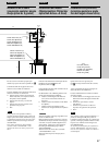
English
Detailed view of the mounting
when using the projector
suspension support PSS-610
Français
Vue détaillée du montage lors
de l'utilisation du support de
suspension du projecteur
PSS-610
97.9
(3
7
/8)
68.9
(2
3
/4)
253.5
(10)
146
(
5
3
/4)
166.5
(6
5
/8)
170
(6
3
/4
)
144.5
(5
3
/4
)
216.6
(8
5
/8
)
43
(1
3
/4)
250
(9
7
/8)