


Hardware Setup SY-6BA+
14
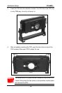
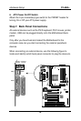
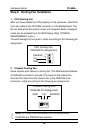
Plug the computer case's front panel devices to the corresponding
headers on the Motherboard.
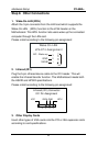
1. Power LED & KeyLock
Plug the Power LED cable into the 5-pin Keylock header.
Some systems may feature a KeyLock function with a front panel
switch for enabling or disabling the keyboard. Connect the KeyLock
switch to the 5-pin Keylock header on the Motherboard.
Please install according to the following pin assignment: pin 1,3 are
for Power LED and pin 4,5 are for Keylock.
2. Reset
Plug the Reset push-button cable into the 2-pin Reset header on the
Motherboard. Pushing the Reset button on the front panel will cause
the system to restart the boot-up sequence.
3. Speaker
Attach the 4-pin PC speaker cable from the case to the Speaker
header on the Motherboard.
4. Turbo LED
Connecting the 2-pin Turbo LED cable to the corresponding Turbo
LED header will cause the LED to light whenever the system is in
Turbo mode.
The manufacturer has permanently set this Motherboard in Turbo
mode due to most hardware and software compliance to turbo
mode.
5. IDE LED
Attach the 2-pin IDE device LED cable to the corresponding IDE
LED header on the Motherboard. This will cause the LED to lighten
when an IDE (HDD, CD-ROM) device is active.