


SY-5EMA+ Quick Start Guide
10
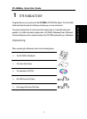
Installation
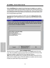
Step 5. Attach Connectors
This section tells how to connect internal peripherals and power supply to the Mainboard.
Internal peripherals include IDE devices (HDD, CD-ROM), Floppy Disk Drive, Chassis Fan,
Front Panel Devices (Turbo LED, Internal Speaker, Reset Button, IDE LED, and KeyLock
Switch.), Wake-On-LAN card, VGA card, Sound Card, and other devices.
For more details on how to connect internal and external peripherals to your new SY-5EMA+
Super 7™ Mainboard, please refer to SY-5EMA+ Mainboard User's Guide and Technical
Reference online manual on CD-ROM.
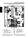
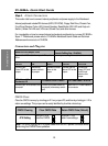
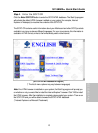
Connectors and Plug-ins
Wake-On-LAN Jumper: JP44
CPU Cooling Fan : CPUFAN
Chassis Cooling Fan : CHAFAN
Connect the WOL cable from your LAN card to
JP44.
Connect you cooling Fan cable to this connector
TB LED SPK RESET IDE LED KB-LOCK
Connect your
Turbo LED to this
jumper
Connect the
speaker cable to
this jumper
Connect the reset
button to this
jumper
Connect the IDE
device LED to this
jumper
Connect the
Power LED and
the KB Lock
switch to this
jumper
IrDA (Infrared Device
Connector): IR
ATX Power On/Off: PWRBT ATX Power Cable : ATX PW
Connect your IrDA device to this
connector
Connect your power switch to
this jumper (momentary switch
type)
Attach the ATX Power cable to
this connector
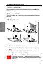
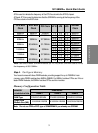
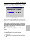
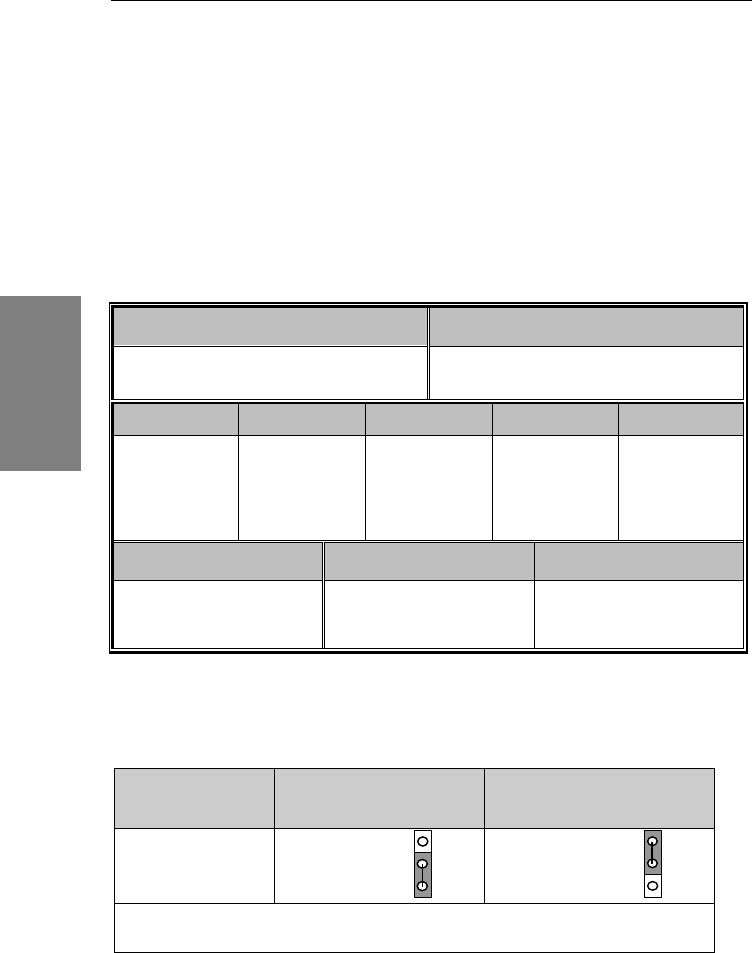
CMOS Clear
Clear the CMOS memory by shorting pin 2-3 on jumper JP5, and then by shorting pin 1-2 to
retain new settings. This jumper can be easily identified by its white colored cap.
CMOS Clearing
Clear CMOS Data
Retain CMOS Data (Default)
JP5 Setting
short pin 2-3 to
clear the CMOS
Short pin 1-2 to
retain new settings
Note: You must unplug the ATX power cable from the ATX power connector when
performing the CMOS Clear operation.
3
2
1
3
2
1