


SY-5SSM & SY-5SSM/5 Quick Start Guide
10
Hardware
Installation
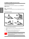
Step 4. Make Connections to the Motherboard
This section tells how to connect internal peripherals and power supply to the Motherboard.
Internal peripherals include IDE devices (HDD, CD-ROM), Floppy Disk Drive, Front Panel
Devices (ACPI LED, Internal Speaker, Reset Button, IDE LED, and KeyLock Switch.),
Wake-On-LAN card, and other devices.
For more details on how to connect internal and external peripherals to your new SY-5SSM
or SY-5SSM/5 Motherboard, please refer to SY-5SSM or SY-5SSM/5 Motherboard User's
Guide and Technical Reference online manual on CD-ROM.
Note: An ATA/66 cable (40-pin, 80-conductor cable) must be used to ensure proper
operation of the Ultra ATA/66 hard drive.
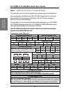
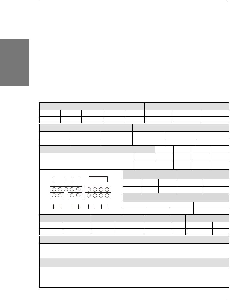
Connectors and Plug-ins
IrDA (Infrared Device Header): IR1 Wake-On-LAN Header: JP44
Pin1 Pin2 Pin3 Pin4 Pin5 Pin1 Pin2 Pin3
VCC None IRRX GND IRTX 5VSB GND MP-Wakeup
CPU Cooling Fan: CPUFAN Chassis Fan: CHAFAN
Pin1 Pin2 Pin3 Pin1 Pin2 Pin3
GND 12V SENSOR GND 12V SENSOR
CD Line-in:CD IN1,CD IN2 Pin1 Pin2 Pin3 Pin4
CD IN1 L G G RConnect the CD Line-in cord from the CR-ROM
device to the matching connector CD IN1 or CD IN2.
CD IN2 G L G R
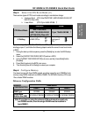
Power LED Keylock
Pin1 Pin2 Pin3
Pin1 Pin2
5V NC GND
Control Pin GND
Speaker
Pin1 Pin2 Pin3 Pin4
5V NC NC Speaker out
HDD LED ACPI LED PWRBT RESET
Pin1 Pin2 Pin1 Pin2 Pin1 Pin2 Pin1 Pin2
LED Anode LED Cathode LED Anode LED Cathode Power On/Off GND Power Good GND
ATX Power On/Off: PWRBT
Connect your power switch to this header (momentary switch type).
To turn off the system, please press this switch and hold down for longer than 4 seconds.
ATX Power Supply: ATX PW
Attach the ATX Power cable to this connector.
When using the Power-On by PS/2 Keyboard function, please make sure the ATX power supply can
take at least 720mA load on the 5V Standby lead (5VSB) to meet the standard ATX specifications.
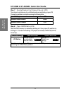
Power LED
Key Lock
Speaker
Reset
PWRBT
Turbo LED
HDD LED
+
+
++
_ _
_
_