6 7
OPERATING INSTRUCTIONS
Operation of the D604, D1204 and D1604 power supplies is simple and straight for-
ward. This sequence of operation is suggested for maximum life and dependability.
Make sure that the Model and Power switches are in the off position and the Push to
Reset button is fully depressed into its socket. Connect light head cable(s) to the Light
Unit Outlet(s) on the power supply. The outlets are wired in parallel so it does not
matter in what sequence light head cables are connected.
Never connect or disconnect light units while power is on. Do not insert or remove
flash tubes while power is on. Your Brown Line power supply is equipped with arc-pro-
tection, but should your light unit or power supply malfunction, or the power cord, or
even the internal wiring in the studio be improperly terminated or defective, the chance
of arc-over when connecting or disconnecting light units is greatly increased. Severe
power supply damage and operator injury may result if arc-over occurs when light units
are being disconnected or connected. To prevent this, you should always turn the power
supply off when disconnecting or connecting light heads.
Never subject a flash tube to more watt-seconds than it is designed to handle.
MW3 and M90 series (non-”Q”) light units have a maximum rating of 400Ws, while “Q”
versions are rated at 1200Ws. M11 light units are rated at 1200Ws* (with new MW9H
flashtubes) and M11Q light units are rated at 2400Ws. We strongly recommend that at
least one light unit in your system is capable of handling the maximum output of your
power supply. If you are not sure if your flash tube and light unit can handle the power
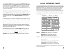
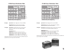
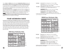
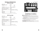
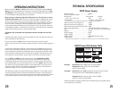
provided by the set up you are using, check pages 25 and 26 and the Power Distribution
Chart on the side of your power supply.
Connect AC power cord into Power Input on power supply, then plug into a properly
grounded outlet. Use proper 3-conductor grounded cord for operator safety and to
reduce self-firing and misfiring caused by static electricity. Set Full/Half/1/4 switch as
desired (Full/Half switch on D604). This switch reduces the total output of the power
supply. Do not switch the Full/Half/1/4 switch until ready light is illuminated. Failure to
follow this procedure may result in damage to the switch.
Plug sync connector into Sync socket and connect the other end to PC cord for camera.
Once the camera is connected, tripping the shutter will automatically trigger the flash.
A slave tripper (Speedotron #23510), may be inserted into the Sync socket in place of
the PC cord. In this mode of operation, the slave will activate the power supply when it
senses a bright flash of light from another light source. If the power supply fails to flash
when exposed to another light source with the slave installed in the sync socket, it may
be necessary to remove the slave, rotate it 180° and reinstall it into the Sync socket.
*New MW9H flashtubes supplied with M11 light units handle up to 1200Ws.
The MW9M flashtubes have a maximum capacity of 1000Ws.
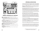
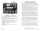
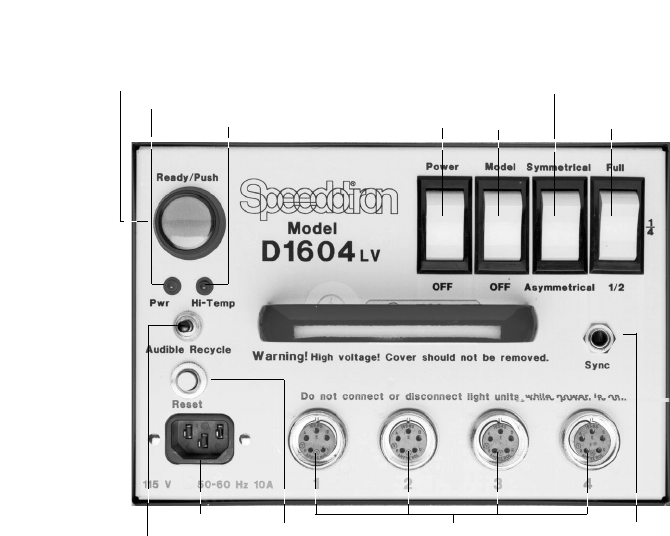
GENERAL DESCRIPTION OF CONTROLS
Power – turns power supply on and off (flashes light units when turning off).
Model – turns model lamp(s) on and off.
Symmetrical/Asymmetrical – controls power distribution. In the symmetrical position,
power is split equally between all lights. In the asymmetrical position, power is
distributed unequally and modeling lamp brightness on light units in outlets 3 and 4
is reduced.
Full/Half (on D604) or Full/Half/1/4 (on D1204 and D1604) – controls the total amount
of power delivered to light unit outlets.
Ready/Push to Flash – combination ready light and test flash button. Illuminates in
green to indicate when power supply has recycled to 85%. Pressing the button
when illuminated triggers the flash for testing or open flash applications.
Audible Recycle – controls audible ready tone (on/off).
Power On – green LED illuminates when power switch is turned on.
Hi-Temp – red LED lights, alarm tone sounds, when internal heat becomes excessive.
Sync – socket for sync extension or slave.
Push to Reset – resets circuit breaker. Circuit breaker disables power supply in case of
malfunction.
Power Input – socket for AC power cord.
Light Unit Outlets (4) – sockets for connecting from one to four light units to power
supply.
Ready/Push to flash button
Power on LED
Hi-temp LED
Symmetrical/Asymmetrical
Power Model
Full/Half/Quarter
Power input
Push to reset
Sync
Light unit outlets
Audible recycle


