


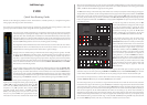
With signal routed onto the main busses, you need to choose how those busses will be submixed to the 5.1 output of the
console. Stabbing the MIX SETUP then Main Mix menu boxes on-screen will bring up the mix matrix:
The 12 main busses feed the matrix from the top,
and any crosspoints (yellow) route those signals
out to the MIX 5.1 outputs on the right. There is
also a ST MIX output which can be used for to
feed the cue system, or for fold downs to any
system output. There is an 8 channel insert
which is set up on the right of this display (here
shown normalled with the MixSnd insert send
signals). This is switched with the MIX INSERT
button in the upper left side of the centre section,
next to the mix compressor (see below). The
eight grey boxes below the matrix are used to
store and recall matrix presets. To recall a preset
simply stab on it (the 5.1/fold preset is shown in
the graphic).
The four rows of boxes under the Main Bus legend are for creating bus master faders, bus groups, assigning inserts, and
applying delays to each of those 12 busses prior to their entry into the matrix. Stabbing on one of the M Fader boxes and
assigning a number (between 1 and 8) links the master gain of that bus output to one of the eight group master faders in
the centre section. This can be very useful for creating audio sub groups with master fader level control.
Stabbing on one of the Groupboxes and assigning a letter (from A to F) groups the main busses together. Busses in a group
may then have their overall gain adjusted from Offto +10dBusing the GROUP A-Dor GROUPE-F pages on the assignable
control panel (directly above the routing panel in the centre section). From these pages, any and all bus inserts which have
been assigned may be switched in and out for the group. To choose an insert for a bus, stab on the appropriate Insert box
above the matrix and choose the insert return signal from the pop-up which appears (all the signals are arranged in the
same order as the source groups), the insert send is automatically made – this is the same process as configuring a channel
insert, which is done from the central routing panel.
Finally, the Bus Delay row allows a letter to be selected for each bus delay, ganging together the delay controls found in
the MAIN DELAY page of the assignable control panel. The delays there may be set to compensate for different timing
between subgroups, or to delay the entire mix output of the console up to167 ms in sample accurate steps.
Once the 5.1 mix signals leave the matrix, they pass through the mix insert point,
then the 5.1 mix compressor in the upper left side of the centre section. This is a
6-channel digital compressor with all sidechains and parameters linked together
(shown left). The COMP IN button switches the compressor in circuit. A choice of
main compressor algorithms are available by stabbing the top right box under
the Compressor heading – these include emulations of the analogue SL 4000 G
(named Quad Bus) and SL 9000 J (named Standard).
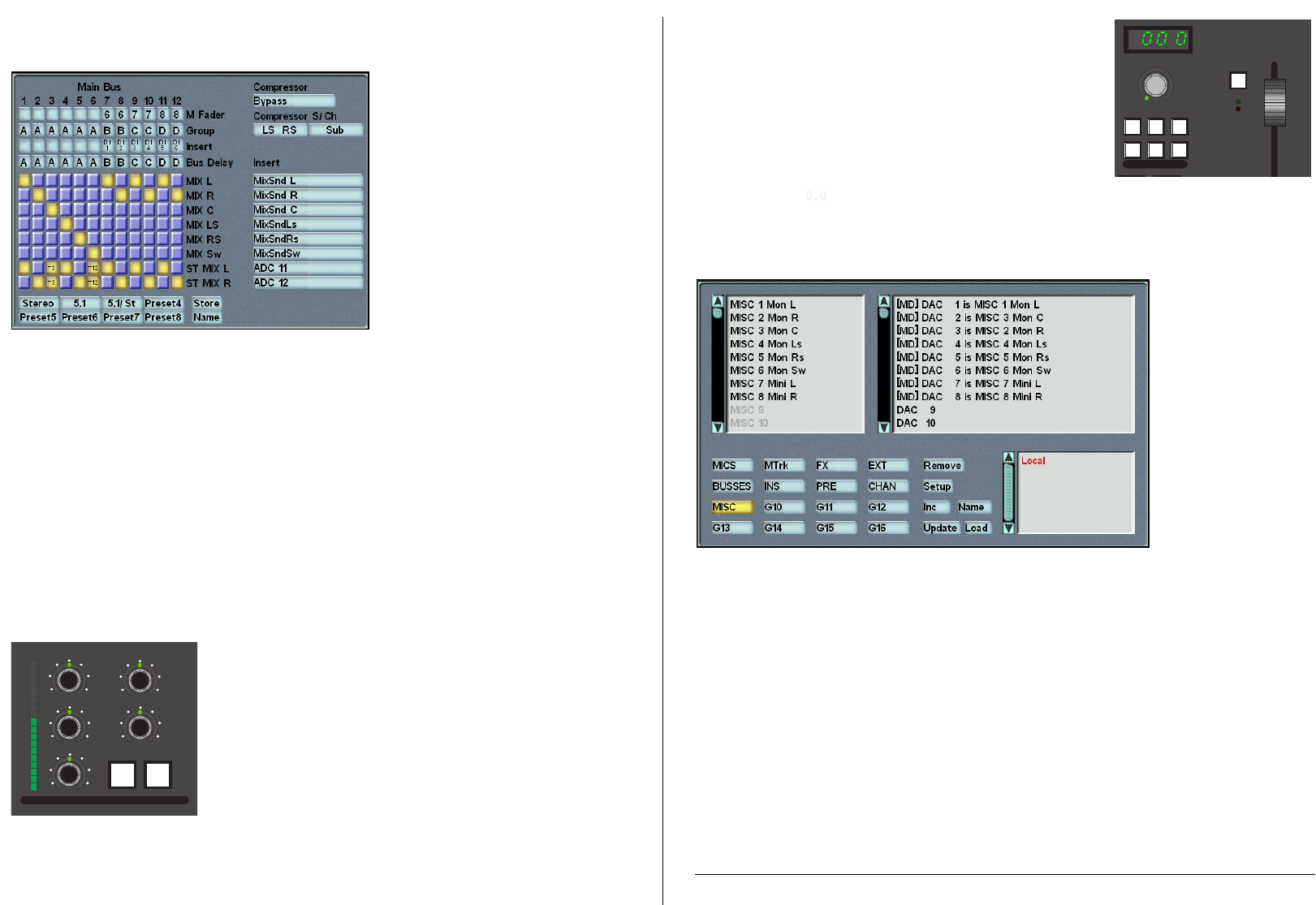
Following the mix insert point and compressor, the master fader is the last signal
processing element before the output busses. This is a long throw, VCAstyle fader
with touch sense and a level match feature for renulling the fader after snapshot
reset, etc.
Whenever the fader’s physical position does not match its actual processing
value, the status button (marked ST, see right) becomes half-lit. Pressing and
holding this button will enable level match, where the STbutton flashes, and the
green trimand red absLEDs next to it also flash to show the direction to the null
point. When the fader is in the correct position, neither abs or trim LED flashes,
and level match mode may be cancelled by pressing the ST button once more.
There is also a master fader offset, which allows the 5.1 output gain to be
trimmed up or down by up to 20dB, regardless of the position of the master
fader. This feature is accessed from the MISC LEVELSarea to the left of the master
fader, by pressing the OFFSET button there and adjusting the pot to the desired
level (this defaults to dB, and is shown in the numeric display).
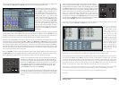
At this point, all that’s left is to route the mix busses out to recorders, distribution, or other destinations. To view or change
output routing, select the MACHINES then Outputs menu boxes on-screen:
This pop-up is divided into
four areas: top left is the list
of signals available from the
source group which is
currently selected at the
bottom left, and top right
gives the hardware outputs
available in the I/O unit
currently selected in the list
to the bottom right. Most of
the I/O in the system will be
under the Local category.
However, any outputs to
remote stageboxes will be
labelled with their network
ID and user name.
To route signals out of the console, select the output from the upper right-hand list, then choose a signal from the upper
left-hand list. You will see the signal name appended to the output name to indicate the route is made.
In the example above you can see that the first eight Local (analogue) outputs have been fed with the 5.1 main and stereo
mini monitor busses (MON L through MINI R). Any output which has a number before it is a digital output – the number
is the sample rate selected for that AES pair. If you want to route a set of consecutive signals to consecutive outputs, route
the first, then select the Inc box and stab on the other outputs in turn – the console then automatically increments the
signals from the source list to each new output. To remove a route, stab on Remove, then on the route in the upper right-
hand list. The other options are mainly used for calibration and system setup, so are not of interest here.
That’s as far as we need to go, and it should get you up and running with audio through the console. With a little
experimentation, you’ll be able to make complex and flexible routing to handle the most demanding of sessions.
If this is your first time on the C200, please let us know how you got on: <info@solid-state-logic.com>
Good luck!
trim
abs
0
5
10
20
15
0
5
10
20
15
ST
AFL
OFF
SET
MISC
TB
RTB
MON
DIM
.
MISC LEVELS
PFL
∞
0
COMP
IN
MIX
INSERT
20
15
10
5
1
THR
RATIO
ATT
MAKE
UP
_
+
RLS
0
1:1
•
CENTRE COMPRESSOR
Routing Guide 82S6C20040A C200