


EVB-EMC2101 User Manual
SMSC EMC2101 Revision 1.5 (12-13-06)
9
3.8 LED Indicators
LEDs indicate the status of the following signals (Table 3.1).
3.9 Jumper Settings
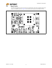
This EVB has many jumper configurations to evaluate all of the features of the EMC2101.
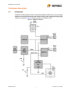
3.9.1 Device Power
To enable one of the 2 devices on the EVB, use jumpers J2 and J3. When a device is selected, the
appropriate LED will light as shown in Table 3.1. Table 3.2 below summarizes the options. Note: only
one device may be active at a time as both devices have the same SMBus address.
3.9.2 Fan Control
To adjust the fan control circuit one 3-way jumper is used. The two settings are DAC mode and PWM
mode. The default setting is PWM which requires the fan to be connected to FAN CONN. 1 and the
JP8 shorted from pin 1-2.
If the linear DAC mode is desired, several things need configured. First, JP8 must be shorted from pin
2-3 and the fan must be connected to FAN CONN. 2. Then, the device must be configured for linear
operation via the ChipMan software. Consult the datasheet for these settings.Table 3.3.
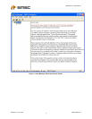
Table 3.1 LED Status Indicators
LED SIGNAL OFF GREEN RED
LED1 ALERT
+3.3V power OFF No ALERT ALERT
LED2 +3.3V +3.3V power OFF +3.3V power ON NA
LED3 Bridge Activity NO Activity on
USB/SMBus Bridge
Activity on
USB/SMBus Bridge
NA
LED4 USB Activity NO Activity on USB port Activity on USB port NA
LED5 EMC2101
Power
U10 power OFF U10 power ON NA
LED6 EMC2101-R
Power
U11 power OFF U11 power ON NA
Table 3.2 Device Power
JUMPER NAME POSITION 1-2 POSITION 2-3
J2 EMC2101 POWER U10 power ON U10 power OFF
J3 EMC2101-R POWER U11 power ON U11 power OFF
Table 3.3 Fan Driver Configuration
FAN DRIVER
CONFIGURATION JP8 FAN CONNECTOR
PWM Position 1-2 P9
DAC Position 2-3 P5