


Ultra Fast USB 2.0 SD/MMC Flash Media Controller
Datasheet
Revision 1.0 (05-27-08) 12 SMSC USB2244/USB2244i
DATASHEET
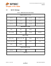
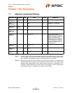
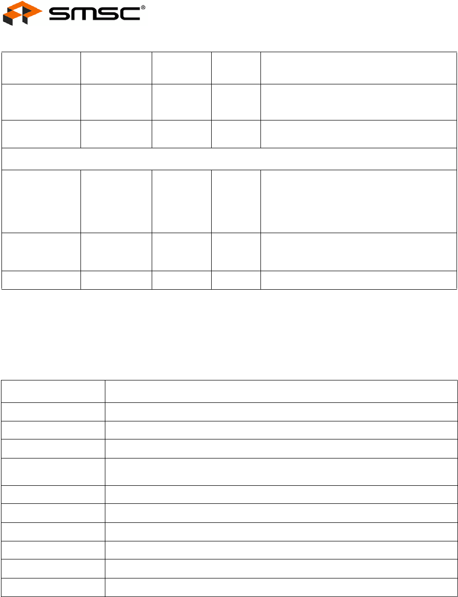
5.2 Buffer Type Descriptions
TEST Input TEST 28 I This signal is used for testing the chip. User
should normally tie this pin low externally if the
test function is not used.
No Connects NC No Connect. No trace or signal should be
routed/attached to these pins.
DIGITAL / POWER
+1.8V Core
power
VDD18 13 All VDD18 pins must be connected together on
the circuit board.
+1.8V core power. This pin must have a 1.0μF
(or greater) ±20% (ESR <0.1Ω) capacitor to
VSS.
3.3V Power &
Regulator Input.
VDD33 6
14
22
3.3V Power & Regulator Input.
Ground VSS SLUG Ground Reference
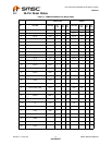
Table 5.3 USB2244/USB2244i Buffer Type Descriptions
BUFFER DESCRIPTION
I Input.
IS Input with Schmitt trigger.
I/O12 Input/Output buffer with 12mA sink and 12mA source.
I/O200 Input/Output buffer 12mA with FET disabled, 100/200mA source only when the FET is
enabled.
I/O12PU Input/Output buffer with 12mA sink and 12mA source with a pull-up resistor.
O12 Output buffer with 12mA source.
ICLKx XTAL clock input.
OCLKx XTAL clock output.
I/O-U Analog Input/Output Defined in USB specification.
I-R RBIAS.
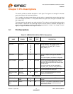
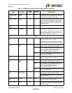
Table 5.2 USB2244/2244i 36-Pin QFN Pin Descriptions (continued)
NAME SYMBOL
36-PIN
QFN
BUFFER
TYPE DESCRIPTION