


2-Port USB 2.0 Hub Controller
Datasheet
Revision 2.3 (08-27-07) 26 SMSC USB2502
DATASHEET
5.3.4 Slave Device Time-Out
According to the SMBus Specification, V1.0 devices in a transfer can abort the transfer in progress
and release the bus when any single clock low interval exceeds 25ms (T
TIMEOUT, MIN
). Devices that
have detected this condition must reset their communication and be able to receive a new START
condition no later than 35ms (T
TIMEOUT, MAX
).
Note: Some simple devices do not contain a clock low drive circuit; this simple kind of device typically
resets its communications port after a start or stop condition.
5.3.5 Stretching the SCLK Signal
The Hub supports stretching of the SCLK by other devices on the SMBus. The Hub does not stretch
the SCLK.
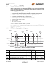
5.3.6 SMBus Timing
The SMBus Slave Interface complies with the SMBus AC Timing Specification. See the SMBus timing
in the “Timing Diagram” section.
5.3.7 Bus Reset Sequence
The SMBus Slave Interface resets and returns to the idle state upon a START field followed
immediately by a STOP field.
5.3.8 SMBus Alert Response Address
The SMBALERT# signal is not supported by the Hub.
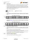
5.3.9 Internal SMBus Memory Register Set
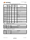
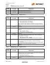
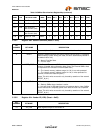
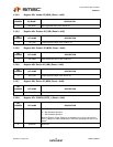
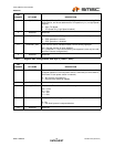
The following table provides the SMBus slave interface register map values.
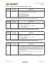
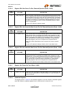
Table 5.4 SMBus Slave Interface Register Map
REG
ADDR R/W REGISTER NAME ABBR
BIT 7
(MSB) BIT 6 BIT 5 BIT 4 BIT 3 BIT 2 BIT 1
BIT 0
(LSB)
00h R/W Status/Command STCD 7 6 5 4 3 2 1 0
01h R/W VID LSB VIDL 7 6 5 4 3 2 1 0
02hR/WVID MSB VIDM76543210
03h R/W PID LSB PIDL 7 6 5 4 3 2 1 0
04hR/WPID MSB PIDM76543210
05hR/WDID LSB DIDL76543210
06h R/W DID MSB DIDM 7 6 5 4 3 2 1 0
07h R/W Config Data Byte 1 CFG1 7 6 5 4 3 2 1 0
08h R/W Config Data Byte 2 CFG2 7 6 5 4 3 2 1 0
09h R/W Non-Removable
Devices
NRD76543210
0Ah R/W Port Disable (Self) PDS 7 6 5 4 3 2 1 0
0Bh R/W Port Disable (Bus) PDB 7 6 5 4 3 2 1 0