


USB 2.0 Hi-Speed Hub Controller
Datasheet
SMSC USB251x 33 Revision 1.0 (3-11-09)
DATASHEET
Chapter 8 Configuration Options
8.1 Hub
SMSC’s USB 2.0 hub is fully specification compliant to the Universal Serial Bus specification, version
2.0, April 27, 2000 (12/7/2000 and 5/28/2002 Errata). Please reference Chapter 10 (Hub specification)
for general details regarding hub operation and functionality.
The hub provides 1 Transaction Translator (TT) that is shared by both downstream ports (defined as
Single-TT configuration), The TT contains 4 non-periodic buffers.
8.1.1 Hub Configuration Options
The SMSC hub supports a large number of features (some are mutually exclusive), and must be
configured in order to correctly function when attached to a USB host controller. There are three
principal ways to configure the hub: SMBus, EEPROM, or by internal default settings (with or without
configuration option over-rides). In all cases, the configuration method will be determined by the
CFG_SEL[2], CFG_SEL[1] and CFG_SEL[0] pins immediately after RESET_N negation. Please refer
to Table 8.1, "Hub Configuration Options" for more information.
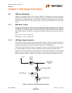
8.1.2 SMBus or EEPROM Interface
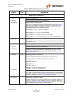
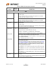
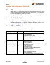
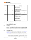
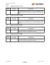
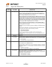
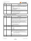
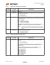
Table 8.1 Hub Configuration Options
CFG_SEL[2] CFG_SEL[1] CFG_SEL[0] DESCRIPTION
0 0 0 Internal Default Configuration without any over-rides
Strap options enabled
Self-powered operation enabled
LED mode = Speed (when available on package)
Individual power switching
Individual over-current sensing
0 0 1 Configured as an SMBus slave for external download of
user-defined descriptors
Strap options disabled
All settings are controlled by registers as set by the user
0 1 0 Internal Default Configuration
Strap options enabled
Bus-powered operation
LED mode = USB (when available on package)
Individual power switching
Individual over-current sensing
01 12-Wire I
2
C EEPROMS are supported
Strap options disabled
All settings are controlled by registers as set by the user