


4th Generation USB 2.0 Flash Media Controller with Integrated Card Power FETs & HS Hub
Datasheet
Revision 1.6 (06-20-08) 14 SMSC USB2601/USB2602
DATASHEET
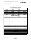
Chapter 6 Pin Descriptions
This section provides a detailed description of each signal. The signals are arranged in functional
groups according to their associated interface.
The “n” or “_N” symbol in the signal name indicates that the active, or asserted state occurs when the
signal is at a low voltage level. When “n” is not present before the signal name (or “_N” after the signal
name), the signal is asserted when at the high voltage level.
The terms assertion and negation are used exclusively. This is done to avoid confusion when working
with a mixture of “active low” and “active high” signal. The term assert, or assertion indicates that a
signal is active, independent of whether that level is represented by a high or low voltage. The term
negate, or negation indicates that a signal is inactive.
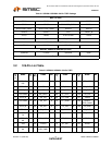
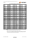
6.1 PIN Descriptions
NAME SYMBOL
BUFFER
TYPE DESCRIPTION
UPSTREAM USB INTERFACE
USB Bus Data USBUP_DM
USBUP_DP
IO-U These pins connect to the Upstream USB bus data
signals.
Detect Upstream
VBUS Power
VBUS_DET I/O12 Detects state of Upstream VBUS power. The SMSC
Hub monitors VBUS_DET to determine when to assert
the internal D+ pull-up resistor (signalling a connect
event).
When designing a detachable hub, this pin must be
connected to the VBUS power pin of the USB port that
is upstream of the hub.
For self-powered applications with a permanently
attached host, this pin must be pulled-up to either 3.3V
or 5.0V (typically VDD33).
3-PORT USB INTERFACE
USB Bus Data USBDN_DM
[4:2]
USBDN_DP
[4:2]
IO-U These pins connect to the Downstream USB bus data
signals.
USB Power Enable PRTPWR[4:2] I/O12 Enables power to USB peripheral devices
(downstream).
The active signal level of the PRTPWR[4:2] pins is
determined by the Power Polarity Strapping function of
the PRTPWR_POL pin.
Port Power Polarity
Strapping
PRTPWR_POL I/O12 Port Power Polarity strapping determination for the
active signal polarity of the PRTPWR[4:2] pins.
While RESET_N is asserted, the logic state of this pin
will (though the use of internal combinatorial logic)
determine the active state of the PRTPWR[4:2] pins in
order to ensure that downstream port power is not
inadvertently enabled to inactive ports during a
hardware reset.
‘1’ = PRTPWR[4:2] pins have an active ‘high’ polarity
‘0’ = PRTPWR[4:2] pins have an active ‘low’ polarity