


4th Generation USB 2.0 Flash Media Controller with Integrated Card Power FETs & HS Hub
Datasheet
Revision 1.6 (06-20-08) 22 SMSC USB2601/USB2602
DATASHEET
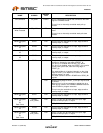
7.2 Operating Conditions
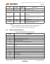
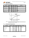
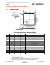
Figure 7.1 Supply Rise Time Model
Note 7.3 When powering the device, the maximum power supply ramp time should be set at a rate
faster than 400 micro seconds. This speed is important to ensure that the device resets
properly. Measure rise time at 10% and 90%.
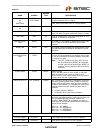
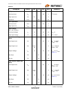
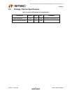
7.3 DC Electrical Characteristics
PARAMETER SYMBOL MIN MAX UNITS COMMENTS
Operating Temperature T
A
0 70 °C *Ambient temperature in still air.
1.8V supply voltage V
DD18,
V
DD18PLL
1.62 1.98 V
3.3V supply voltage V
DD33,
V
DDA33
3.0 3.6 V
3.3V supply rise time t
RT
0400 μs (See Figure 7.1, "Supply Rise Time
Model")
Voltage on XTAL1 -0.3 V
DDA33
V
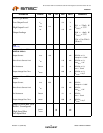
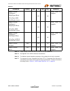
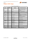
PARAMETER SYMBOL MIN TYP MAX UNITS COMMENTS
I,IPU & IPD Type Input Buffer
Low Input Level
High Input Level
Pull Down
Pull Up
V
ILI
V
IHI
PD
PU
2.0
72
58
0.8 V
V
μA
μA
TTL Levels
t
10%
10%
90%
Voltage
t
RT
t
90%
Time
100%
3.3V
VSS
VDD33