


– 49 –
APPENDIX
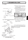
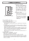
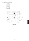
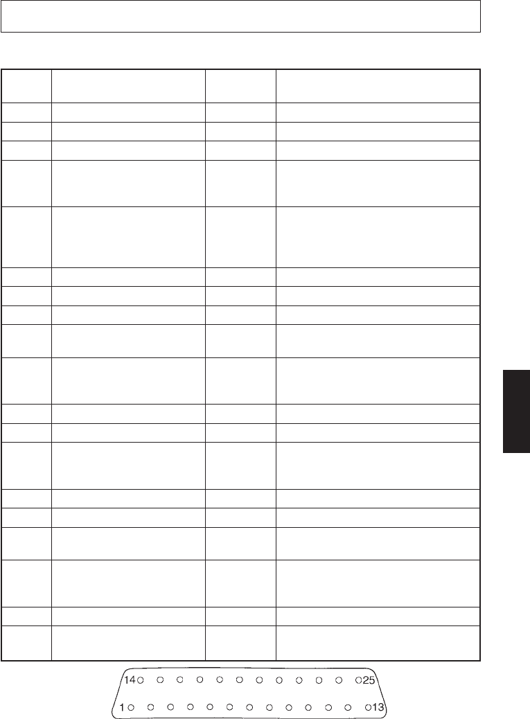
Serial interface connector
APPENDIX
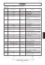
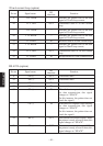
Connectors and Signals (Serial Interface)
RS-232C
Pin no. Signal name
I/O
Function
direction
1 F-GND — Frame ground
2 TXD OUT Transmitted data
3 RXD IN Received data
4 RTS OUT Data transmission request signal. This
is always “SPACE” when the printer is
turned on.
5 CTS IN This signal changes to “SPACE” when
host computer is ready to transmit data.
(In this instance, the printer does not
check this signal.)
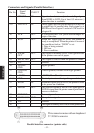
6 N/C Not connected
7 S-GND — Signal ground
8 N/C Not connected
9-10 N/C This pin is used when using the op-
tional interface board.
11 RCH OUT This signal changes to “SPACE” when
the printer is ready to receive data. (The
signal line is same as pin 20.)
12 N/C Not connected.
13 S-GND — Signal ground
14 FAULT OUT When a printer error occurs (such as
paper out, mechanical error, etc.), this
signal is set to “MARK”.
15 Multi-printer TXD OUT Diode coupled TXD
16 Multi-printer DTR OUT Diode coupled DTR
17 to 19 N/C This pin is used when using the op-
tional interface board.
20 DTR OUT Data terminal ready signal. When the
printer is ready to receive data, this
signal changes to “SPACE”.
21-22 N/C Not connected
23 to 25 N/C This pin is used when using the op-
tional interface board.