


Instruction Manual
3
Preparing Your Site
1. Determine where the local video source (i.e. computer) will be located and set up the
device.
2. Determine where the remote display will be located and place/mount the display
appropriately.
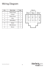
3. If you are using surface cabling, ensure you have enough Cat5 unshielded twisted pair
(UTP) Ethernet cabling to connect the Local Unit to the Remote Unit’s location, and
that each end is terminated with a RJ45 Ethernet connector. The cabling should not go
through any networking equipment (i.e. router, switch).
OR
If you are using premise cabling, ensure that the Cat5 unshielded twisted pair (UTP)
Ethernet Cabling between the Local Unit and the Remote Unit has been properly
terminated in a wall outlet in each location and there is a patch cable long enough to
connect the Remote Unit and the Local Unit to their respective outlets. The cabling
should not go through any networking equipment (i.e. router, switch).
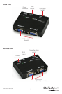
Installing the Local Unit
1. Place the Local Unit near the local (source) computer.
2. Switch o the computer and disconnect any existing VGA cables.
3. If desired, connect the VGA cable from the local computer display(s) to the “Monitor”
ports on the Local Unit. This will enable you to see video locally while an image is
transmitted to the remote display. You may choose to connect up to two local displays,
one for each “Monitor” port. Both outputs display the same image.
4. Connect a male-to-female DE-15 VGA cable (not provided) to the VGA Output on the
local computer. Connect the opposite end to the VGA IN port on the Local Unit.
5. Connect the Cat5 cable connection to the “CAT5 OUT” on the Local Unit.
6. Connect the Power Adapter (provided) into an appropriate power source and plug the
opposite end into the power connector on the Local Unit. The POWER LED will light up.