


Instruction Manual
3
Pin # Description
1 Left channel signal
2 Left channel ground
3 Right channel ground
4 Right channel signal
Pin # Description
1 Right channel ground
2 Right channel signal
3 Left channel ground
4 Left channel signal
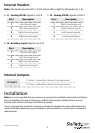
Internal Headers
Note: The header pinout is Pin 1 to Pin 4 from left to right for all headers (6, 7, 8).
6. J1 - Analog CD/IN: Signals: L-G-G-R
7. J2 - Analog CD/IN: Signals: G-R-G-L
Pin # Description
1 Left channel signal
2 Left channel ground
3 Right channel ground
4 Right channel signal
8. J3 - Auxiliary Input: Signals: L-G-G-R.
Internal Jumpers
JP1 & JP2
1-2 close - Center/Bass channel in normal mode
2-3 close - Center/Bass channel in inverse mode
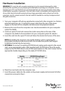
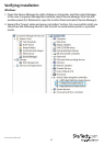
Installation
Note: It is recommended that you remove any previously installed sound cards and drivers
prior to installing this card to avoid any conicts. If previously installed drivers are not
removed, this sound card may not function properly.
If your computer has on-board sound you will need to disable it on the motherboard. For
more information please see your computer’s documentation or contact your computer’s
manufacturer.