


Instruction Manual
4
Hardware Installation
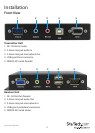
Transmitter Unit
1. Connect the included USB cable between the computer/KVM and the USB port on
the Transmitter Unit. This also provides power to the Transmitter Unit.
Optional: A 5V DC power adapter can be used for backup or if not using the USB
cable. This power adapter is not included.
2. Connect a male/female VGA cable between the computer/KVM and the “Video In”
VGA connector on the Transmitter Unit.
Optional: Connect a monitor to the “Video Out” VGA connector on the Transmitter
Unit for local video output.
3. Connect the Cat5e cable from the RJ45 “Link” port to the rst Receiver Unit in the
series.
4. Optional: If transmitting audio, connect the speaker/line out on the computer/KVM
sound card to the “Audio-In“ 3.5mm connector on the Transmitter Unit.
5. Optional: Connect computer speakers to the “Audio-Out” 3.5mm port for local
audio output.
6. Optional: If you wish to receive audio input (microphone), connect the mic-in on
the computer/KVM sound card to the “Mic-out” connector on the Transmitter Unit.
7. Optional: Connect the serial port on the computer/KVM to DB9 “Serial” port using
the appropriate type of serial cable (i.e. straight-through cable from a PC).
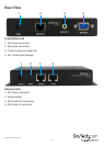
Receiver Unit
1. Connect the included 5V power adapter to the “Power” connector.
2. Connect a monitor to the “VGA-Out” connector.
3. Connect a USB keyboard/mouse to the USB type A connectors.
4. Connect the Cat5e cable from Transmitter Unit to the “Link In” port.
5. To connect additional Receiver Units, connect a Cat5e cable from the “Link Out”
port, to the “Link In”, of any additional units.
6. Optional: Connect a microphone to the 3.5mm “Mic-In” port.
7. Optional: Connect computer speakers to the 3.5mm “Audio-Out” port.
8. Optional: Connect an RS-232 serial device to the DB9 “Serial” port.
Driver Installation
No drivers or additional software need to be installed on the host computer.