


SATA DE110 User's Guide - Rev. A03 StorCase Technology, Inc.
Installation 11
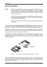
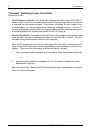
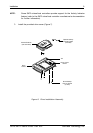
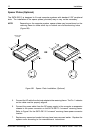
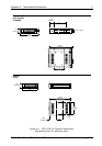
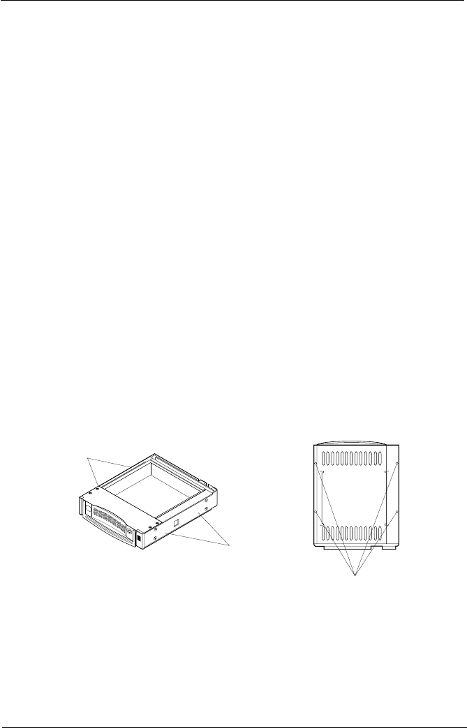
Figure 8A: Receiving Frame Mounting Holes
Mounting
Holes
(Right)
Mounting
Holes
(Left)
0837
Mounting
Holes
(Bottom)
Front of Unit
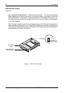
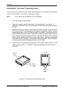
InstallingtheUniversal ReceivingFrame
The drive should be installed into the carrier before installing the universal receiving frame
into the mounting bay of a computer or expansion chassis.
NOTE: Use a #2 Phillips screwdriver for this procedure.
1. Turn OFF power to the computer.
2. Open the computer system according to the manufacturers instructions. If
necessary, temporarily remove any expansion boards that may make installation
difficult.
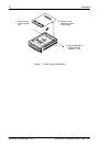
3. With the drive carrier locked in place inside the receiving frame, install the SATA
DE110 into the 5.25 drive opening in the computer or expansion chassis. Use the
appropriate guides to position the Data Express, and fasten it into place with the four
(4) #6-32 Phillips screws provided. Figure 8A illustrates the location of the mounting
holes. Mounting holes are provided on each side and the bottom of the receiving
frame to accommodate a variety of mounting configurations. Use the mounting holes
which best suit the computer or expansion chassis configuration. Note that bottom
mounting holes require self-tapping screws (not provided).
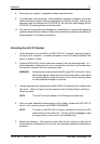
4. Adjust the front of the receiving frame so the carrier slides freely in and out on the
receiving frame guides. The position of adjoining peripheral units may require
adjustment.