


35
APPENDIX
C
T1 Inverted Data and Clock Signals
This appendix includes the following topics:
■ “Data Signal Inversion” on page 35
■ “Clock Signal Inversion” on page 37
Data Signal Inversion
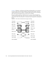
The requirement for inverting data signals arises from the “ones density” problem
you encounter with most T1 transmission lines in North America. The T1
transmission scheme uses a signaling mechanism known as Alternate Mark Inversion
(AMI), in which one bits are represented by a positive or negative pulse, while zero
bits are represented by the absence of a pulse. In this scheme, the polarity of each
pulse must be the opposite of the polarity of the pulse which immediately preceded
it. This signaling scheme makes it possible to embed a reference clock for the data
into the data stream itself.
Various types of T1 transmission equipment, such as Data Service Units (DSU),
Channel Service Units (CSU), repeaters, and various telephone central office
equipment, must be able to keep a phase locked loop (PLL) circuit locked on to this
reference clock. This PLL circuit uses the pulses generated when one bits are
transmitted to lock the embedded clock to a local reference oscillator. To keep the
PLL circuit locked on the extracted clock, a certain density of pulses (one bits) must
be guaranteed. For North American T1 lines, the density requirement dictates that at
least one out of every 16 bits must be a one (see AT&T Technical Publication 62411).
Another way of stating this is that no more than 15 consecutive zero bits can occur
anywhere in the data stream.
T1 lines were originally intended to carry voice traffic, wherein the digitized voice
signals could be altered to meet the ones-density requirement by forcing every eighth
bit of a voice channel to be a one. This practice introduces a small—but virtually