


5-8
S
UPERSERVER 6015B-UR/6015B-U/6015B-NTR/6015B-NT User's Manual
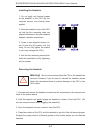
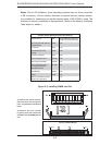
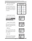
Top View of DDR2 FBD Slot
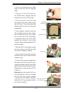
Figure 5-3. Installing DIMM into Slot
To Install: Insert module vertically
and press down until it snaps into
place. Pay attention to the bottom
notch.
To Remove: Use your thumbs
to gently push each release tab
outward to free the DIMM from the
slot.
DDR2 FBD DIMM
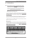
Possible System Memory Allocation & Availability
System Device Size Physical Memory Remaining
(4 GB Total System Memory)
Firmware Hub fl ash memory
(System BIOS)
1 MB 3.99
Local APIC 4 KB 3.99
Area Reserved for the
chipset
2 MB 3.99
I/O APIC (4 Kbytes) 4 KB 3.99
PCI Enumeration Area 1 256 MB 3.76
PCI Express (256 MB) 256 MB 3.51
PCI Enumeration Area 2
(if needed) -Aligned on
256-MB boundary-
512 MB 3.01
VGA Memory 16 MB 2.85
TSEG 1 MB 2.84
Memory available to System
BIOS & OS applications
2.84
Notes: Due to OS limitations, some operating systems may not show more than
4 GB of memory. Due to memory allocation to system devices, memory remain-
ing available for operational use will be reduced when 4 GB of RAM is used. The
reduction in memory availability is disproportional. (Refer to the Memory Availability
Table below for details.)