


Chapter 5: Advanced Serverboard Setup
5-15
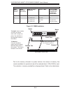
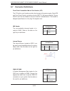
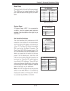
Serial Ports
One serial port is included on the serverboard.
The COM port is located beside the VGA
port. See the table on the right for pin defi ni-
tions.
(NC: No Connection)
Serial Port Pin Defi nitions
Pin Defi nitions
Pin # Defi nition Pin # Defi nition
1 DCD 6 DSR
2 RXD 7 RTS
3 TXD 8 CTS
4 DTR 9 RI
5 Ground 10 NC
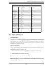
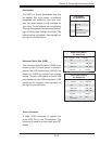
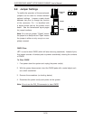
System Reset
If System Reset (JRST1) is connected to
a switch, then the system reset feature is
enabled. See the table on the right for pin
defi nitions.
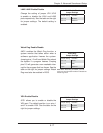
Alarm Reset
Pin Defi nitions
Pin# Defi nition
Pin 1 3.3V
Pin 2 Ground
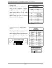
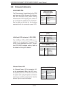
Unit Identifi er Switches
Two Unit Identifi er (UID) switches and LED
indicators are located on the serverboard.
The Front Panel UID Switch is located at pin
16 on JF2. The Rear UID Switch is located at
SW1 next to the Infi niBand Connector. The
Front Panel UID LED is located at pin 17 of
JF2, and the Rear UID LED is located at LE4.
When you press the UID switch on the front
panel or on the back panel, both Rear UID
LED and Front Panel UID LED indicators will
be turned on. Press the UID switch again to
turn off both LED Indicators. These UID Indi-
cators provide easy identifi cation of a system
unit that may be in need of service. See the
table on the right for pin defi nitions.
Note: UID LED is supported by the physical
switch or the BMC. When it is controlled by
the physical switch, it will stay solid. When it
is controlled by the BMC, it will blink.
UID Switch
Pin Defi nitions
Pin# Defi nition
1 Ground
2 Ground
3 Button In
4 Ground
UID Switches & LEDs
Description Location
FP Switch Pin 16 on JF2
Rear Switch SW1
FP UID LED
(Blue LED)
Pin 17 on JF2
Rear UID LED LE4