


H8QG6/i+-F Serverboard User's Manual
2-10
2-7 Connector Defi nitions
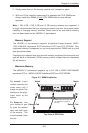
Power Connectors
A 24-pin main power supply connector(JPW1)
and three 8-pin CPU PWR connectors
(JPW2/JPW3/JPW4) on the motherboard.
These power connectors meet the SSI EPS
12V specifi cation. In addition to the 24-pin
ATX power connector, the 12V 8-pin CPU
PWR connectors at JPW2/JPW3/JPW4 must
also be connected to your power supply. See
the table on the right for pin defi nitions.
Warning: To prevent damage to the power
supply or motherboard, please use a power
supply that contains a 24-pin and three
8-pin power connectors. Be sure to connect
these connectors to the 24-pin (JPW1) and
the three 8-pin (JPW2 and JPW4) power
connectors on the motherboard. Failure in
doing so will void the manufacturer warranty
on your power supply and motherboard.
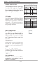
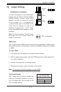
PW_ON Connector
The PW_ON connector is on pins 15 and 16
of JF1. This header should be connected to
the chassis power button. See the table on
the right for pin defi nitions.
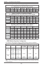
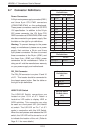
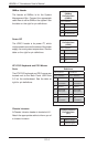
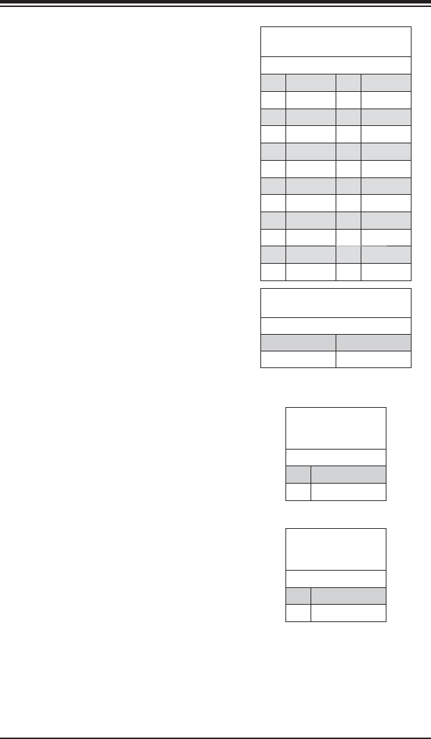
ATX Power 24-pin Connector
Pin Defi nitions
Pin# Defi nition Pin # Defi nition
13 +3.3V 1 +3.3V
14 -12V 2 +3.3V
15 COM 3 COM
16 PS_ON 4 +5V
17 COM 5 COM
18 COM 6 +5V
19 COM 7 COM
20 Res (NC) 8 PWR_OK
21 +5V 9 5VSB
22 +5V 10 +12V
23 +5V 11 +12V
24 COM 12 +3.3V
Required Connection
Power Button
Pin Defi nitions
(JF1)
Pin# Defi nition
15 PW_ON
16 Ground
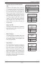
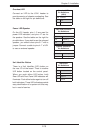
12V 8-pin PWR Connector
Pin Defi nitions
Pins Defi nition
1 through 4 Ground
5 through 8 +12V
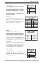
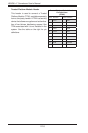
HDD/FP UID Switch
The HDD/UID Switch connections are
located on pins 13/14 of JF1. Attach a
hard-drive LED cable to display HDD or
SATA activities. This connection can also
be used as a front panel UID (Unit Identifi
er) switch. The UID LED on Pin 7 of JF1
works in conjunction with this UID Switch.
When the user presses and releases the UID
switch, the UID LED will be turned on or off
to indicate the location of the unit. (Refer to
Page 2-11 for more details.)
HDD/UID Switch
Pin Defi nitions
(JF1)
Pin# Defi nition
13 UID Signal/3.3V
14 HDD Active