


2-10
H8QM3-2/H8QMi-2 User's Manual
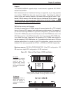
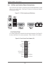
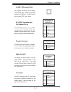
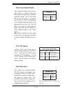
Fan Headers
The serverboard has nine fan head-
ers, which are designated FAN1
through FAN9. Fans speed may be
set to full or variable speed with a
BIOS setting. See the table on the
right for pin defi nitions.
Note: when using active heatsinks,
FAN4 is for CPU1, FAN3 is for CPU2,
FAN7 is for CPU3 and FAN8 is for
CPU4.
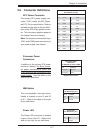
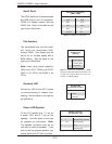
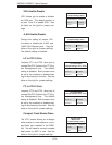
Serial Ports
The COM1 serial port is located beside
the USB ports on the I/O backplane.
COM2 is a header located near the
SIMLC slot. Refer to the table on the
right for pin defi nitions.
Note: NC indicates no connection.
Serial Port Pin Defi nitions
(COM1, COM2)
Pin # Defi nition Pin # Defi nition
1 DCD 6 DSR
2 RXD 7 RTS
3 TXD 8 CTS
4 DTR 9 RI
5 Ground 10 NC
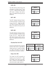
Fan Header
Pin Defi nitions
(FAN1-9)
Pin# Defi nition
1 Ground (Black)
2 +12V/9V (Red)
3 Tachometer
Note: Fan speed may controlled by a BIOS
setting to change with system temperature. As
a result, pin 2 may be either 12V or 9V. See
Chapter 4 for BIOS settings.
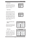
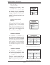
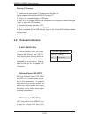
Overheat LED
Connect an LED to the JOH1 header
to provide warning of chassis over-
heating. See the table on the right for
pin defi nitions.
Overheat LED
Pin Defi nitions (JOH1)
Pin# Defi nition
1 +3.3V
2 OH Active
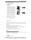
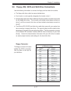
Power LED/Speaker
On the JD1 header, pins 1-3 are for
a power LED, pins 4-7 are for the
speaker. See the table on the right
for speaker pin definitions. Note:
The speaker connector pins are for
use with an external speaker. If you
wish to use the onboard speaker, you
should close pins 6-7 with a jumper.
Speaker Connector
Pin Defi nitions (JD1)
Pin # Function Defi nition
4 + Speaker data (red wire)
5 Key No connection
6 Key
7 Speaker data