


Chapter 2: Installation
2-9
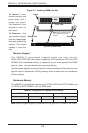
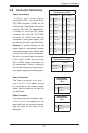
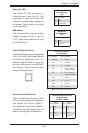
DIMM Module Population Confi guration
For memory to work properly, follow the tables below for memory installation:
Per Channel DIMM Populations Options
DIMM Type DIMM A DIMM B Max. MHz,
1.5V DIMMs
Max. MHz,
1.35V DIMMs
(6-core Only)
Max. GB/
Channel
Unbuffered
DIMM
(UDIMM)
SR or DR Empty
1600 MHz 1333 MHz 8GB
SR SR
1333 MHz 1333 MHz 8 GB
DR DR
1066 MHz 1066 MHz 16 GB
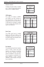
Registered
DIMM
(RDIMM)
SR or DR Empty
1600 MHz 1333 MHz 16 GB
SR SR
1333 MHz 1333 MHz 16 GB
DR DR
1066 MHz 1066 MHz 32 GB
QR Empty 1333 MHz 1066 MHz 32 GB
QR QR 800 MHz 800 MHz 64 GB
Note 1: Due to OS limitations, some operating systems may not show more than
4 GB of memory.
Note 2: Due to memory allocation to system devices, the amount of memory that
remains available for operational use will be reduced when 4 GB of RAM is used.
The reduction in memory availability is disproportional.
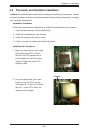
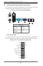
2-6 PCI Expansion Cards
A riser card is used to support one standard size (full height full length) PCI
expansion card.
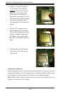
Installing a PCI Expansion Card
1. Confi rm that you have the correct riser card for your chassis model and the
add-on card includes a standard bracket.
2. Remove the chassis cover.
3. Install the riser card by sliding card into the appropriate slot in the
serverboard.
4. Choose the PCI slot shield in which to place the add-on card.
5. In that slot, open the PCI slot shield lever and slide the shield sideways.
6. From inside the chassis, remove the PCI slot shield.
7. Slide the add-on card into the riser card and attach the add-on card bracket
in place of the PCI slot shield.
8. Secure the add-on card by closing the PCI slot shield lever.
9. Connect cables to the add-on card as necessary.