


H8SCM(-F) SERVERBOARD USER'S MANUAL
2-12
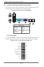
NIC2 (Activity) LED
The LED connections for LAN2 are on
pins 9 and 10 of JF1. Attach LAN LED
cables to display network activity. See
the table on the right for pin defi nitions.
HDD LED
The HDD LED connection is located
on pins 13 and 14 of JF1. Attach the
hard drive LED cable here to display
disk activity (for any hard drives on the
system, including SAS, Serial ATA and
IDE). See the table on the right for pin
defi nitions
NIC1 LED
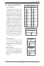
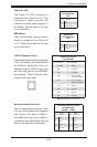
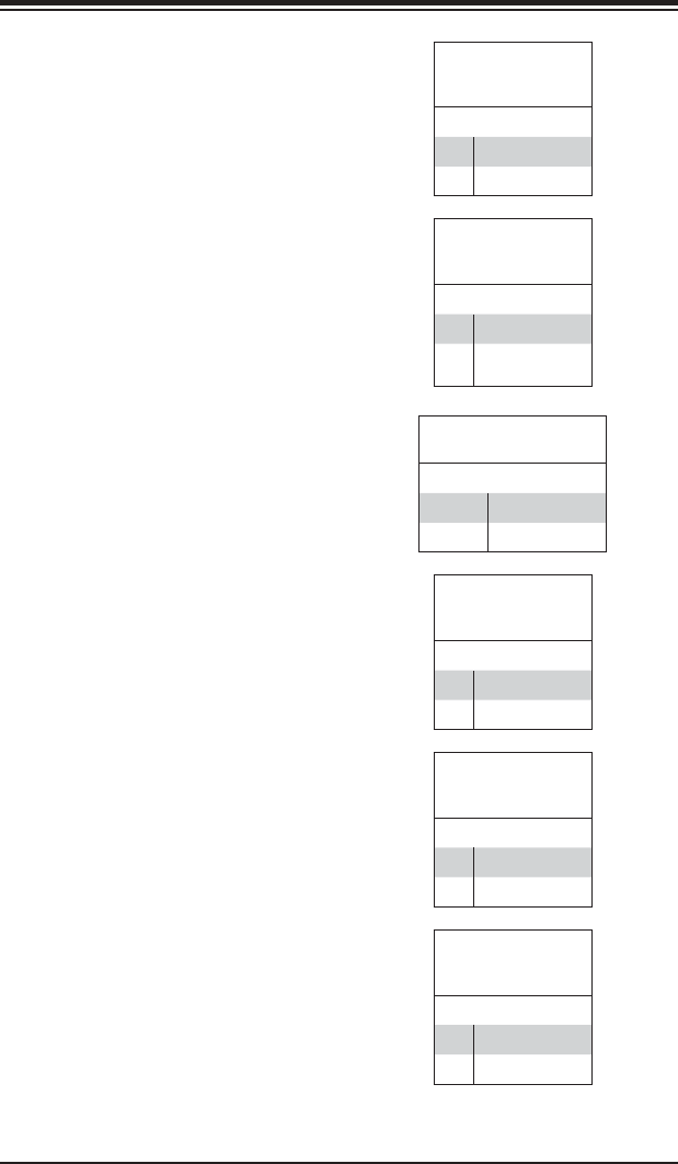
Pin Defi nitions
(JF1)
Pin# Defi nition
11 Vcc
12 Activity
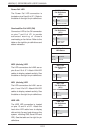
NIC2 LED
Pin Defi nitions
(JF1)
Pin# Defi nition
9 Vcc
10 Activity
NIC1 (Activity) LED
The LED connections for LAN1 are on
pins 11 and 12 of JF1. Attach LAN LED
cables to display network activity. See
the table on the right for pin defi nitions.
HDD LED
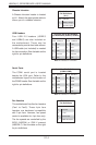
Pin Defi nitions
(JF1)
Pin# Defi nition
13 Vcc
14 HD LED
Overheat/Fan Fail LED (OH)
Connect an LED to the OH connection
on pins 7 and 8 of JF1 to provide
advanced warning of chassis
overheating or fan failure. Refer to the
table on the right for pin defi nitions and
status indicators.
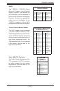
OH/Fan Fail LED
Pin Defi nitions
(JF1)
Pin# Defi nition
7 Vcc
8 OH/Fan Fail
(Red) LED
OH/Fan Fail
LED Status
State Indication
Solid Overheat
Blinking Fan fail
Power Fail LED
The Power Fail LED connection is
located on pins 5 and 6 of JF1. Refer to
the table on the right for pin defi nitions.
PWR Fail LED
Pin Defi nitions
(JF1)
Pin# Defi nition
5 3.3V
6 Power Fail LED