


2-24
X10SLQ/X10SLQ-L User’s Manual
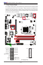
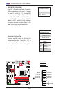
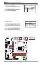
NIC1/NIC2 (LAN1/LAN2)
The NIC (Network Interface Controller)
LED connection for LAN port 1 is located
on pins 11 and 12 of JF1, and the LED
connection for LAN Port 2 is on Pins 9
and 10. NIC1 LED and NIC2 LED are
2-pin NIC LED headers. Attach NIC LED
cables to NIC1 and NIC2 LED indicators
to display network activities. Refer to the
table on the right for pin denitions.
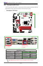
LAN1/LAN2 LED
Pin Denitions (JF1)
Pin# Denition
9/11 Vcc
10/12 Ground
C
A. NIC1 LED
B. NIC2 LED
C. OH/Fan Fail
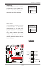
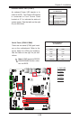
Overheat (OH)/Fan Fail
Connect an LED cable to OH/Fan Fail
connections on pins 7 and 8 of JF1 to
provide warnings for chassis overheat/fan
failure. Refer to the table on the right for
pin denitions.
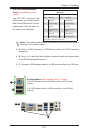
OH/Fan Fail LED
Pin Denitions (JF1)
Pin# Denition
7 Vcc/Blue UID LED
8 OH/Fan Fail LED
OH/Fan Fail Indicator
Status
State Denition
Off Normal
On Overheat
Flash-
ing
Fan Fail
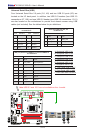
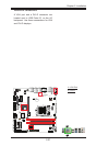
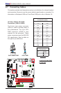
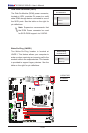
Power Button
OH/Fan Fail LED
1
NIC1 LED
Reset Button
2
HDD LED
Power LED
Reset
PWR
LED_Anode+
LED_Anode+
LED_Anode+
LED_Anode+
Ground
Ground
X
X
NIC2 LED
LED_Anode+
A
B
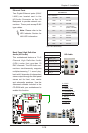
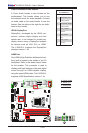
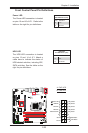
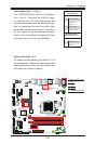
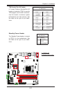
X10SLQ (-L)
Rev. 1.00
MAC CODE
BAR CODE
BIOS
LICENSE
JSD1
JBT1
SP1
JITP1
LED1
LED2
LED3
T-SGPIO1
T-SGPIO2
COM1
COM2
COM3
COM4
JD1
FAN3
FAN2
FAN1
FAN4
JP2
JP1
JLED1
JWD1
JPL2
JPL1
JPAC1
JI2C1 JI2C2
JP5
JP4
JP3
JL1
JWOR1
JHD_AC1
I-SATA2
I-SATA1
I-SATA3
I-SATA0
I-SATA4
JTPM1
JF1
JPW2
USB10/11(3.0)
AUDIO FP
USB6/7
USB8/9
SLOT4 PCI-E 2.0 X4
SLOT5 PCI-E 2.0 X1
HD AUDIO
SLOT7 PCI-E 3.0 X16
USB4/5
LAN2
USB2/3(3.0)
LAN1
HDMI/DP
ALWAYS POPULATE BLUE SOCKET FIRST
UNB NON-ECC DDR3 DIMM REQUIRED
VGA/DVI
KB/MOUSE
USB0/1
CPU FAN
DIMMA1
DIMMA2
DIMMB1
DIMMB2
Battery
JPW1
BIOS
Intel PCH
JBR1
JPME1
JVR1
Not On “-L
Model”
Not On “-L Model”
Not On “-L Model”
Not On “-L
Model”
CPU
Not On “-L Model”
Not On “-L Model”