


Data Sheet: Belleta
®
iEA Series –Single Output Eighth Brick
©2004 TDK Innoveta® Inc.
iEAFullDatasheet 032707 3/29/2007 Revision 2.0
℡
(877) 498
-
0099
36/41
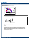
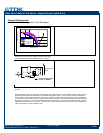
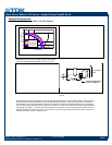
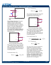
Wind Tunnel Test Setup Figure
Dimensions are
in millimeters and (inches).
Thermal Management:
An important part of the overall system
design process is thermal management;
thermal design must be considered at all
levels to ensure good reliability and lifetime
of the final system. Superior thermal design
and the ability to operate in severe
application environments are key elements
of a robust, reliable power module.
A finite amount of heat must be dissipated
from the power module to the surrounding
environment. This heat is transferred by the
three modes of heat transfer: convection,
conduction and radiation. While all three
modes of heat transfer are present in every
application, convection is the dominant
mode of heat transfer in most applications.
However, to ensure adequate cooling and
proper operation, all three modes should be
considered in a final system configuration.
The open frame design of the power module
provides an air path to individual
components. This air path improves
convection cooling to the surrounding
environment, which reduces areas of heat
concentration and resulting hot spots.
Test Setup: The thermal performance data
of the power module is based upon
measurements obtained from a wind tunnel
test with the setup shown in the wind tunnel
figure. This thermal test setup replicates the
typical thermal environments encountered in
most modern electronic systems with
distributed power architectures. The
electronic equipment in networking, telecom,
wireless, and advanced computer systems
operates in similar environments and utilizes
vertically mounted PCBs or circuit cards in
cabinet racks.
The power module, as shown in the figure,
is mounted on a printed circuit board (PCB)
and is vertically oriented within the wind
tunnel. The cross section of the airflow
passage is rectangular. The spacing
between the top of the module and a parallel
facing PCB is kept at a constant (0.5 in).
The power module’s orientation with respect
to the airflow direction can have a significant
impact on the module’s thermal
performance.
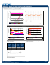
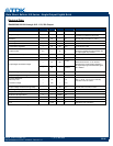
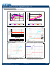
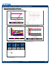
Thermal Derating: For proper application of
the power module in a given thermal
environment, output current derating curves
are provided as a design
guideline on the Thermal Performance
section for the power module of interest.
The module temperature should be
measured in the final system configuration
to ensure proper thermal management of
the power module. For thermal performance
verification, the module temperature should
be measured at the component indicated in
the thermal measurement location figure on
the thermal performance page for the power
module of interest. In all conditions, the
power module should be operated below the
maximum operating temperature shown on
the derating curve. For improved design
margins and enhanced system reliability, the
power module may be operated at
temperatures below the maximum rated
operating temperature.
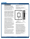
AIRFLOW
Air Velocity and Ambient
Temperature
Measurement Location
A
I
R
F
L
O
W
12.7
(0.50)
Module
Centerline
Air Passage
Centerline
Adjacent PCB
76 (3.0)