


(2/3)
003-01 / 20080820 / e9143_zcb_11.fm
• All specifications are subject to change without notice.
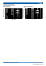
ELECTRICAL CHARACTERISTICS
TYPICAL ELECTRICAL CHARACTERISTICS
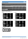
ATTENUATION vs. FREQUENCY CHARACTERISTICS
ZCB2203-11 ZCB2206-11
ZCB2201-M ZCB2203-M
CIRCUIT DIAGRAM
Part No. ZCB2203-11 ZCB2206-11 ZCB2201-M ZCB2203-M
Rated voltage Eac(V) 250 250 250 250
Rated current(A) 3 6 1 3
Test voltage Eac(V)[Between terminal and ground terminal] 1500 1500 1500 1500
Insulation resistance(MΩ)
[DC. 500V, 1min/between terminal and ground terminal]
100min. 100min. 100min. 100min.
Leakage current(mA)
0.75max.
[250V • 60Hz]
0.75max.
[250V • 60Hz]
0.41max.
[250V • 50Hz]
0.41max.
[250V • 50Hz]
DC resistance(mΩ) 500max. 100max. 100max. 80max.
Operating temperature range(°C)[Including self-temperature rise] –25 to +85 –25 to +85 –25 to +85 –25 to +85
With derating over(°C) 55 55 55 55
Temperature rise(°C) 30max. 30max. 30max. 30max.
Attenuation frequency range
(MHz)[+5 to +35°C]
Differential mode at 30dB 2 to 10 2 to 10 2.5 to 20 2.5 to 20
Common mode at 30dB 1 to 10 1 to 10 1 to 30 1 to 30
Weight(g) 45452222
100
80
60
40
20
0
0.1 0.3 1 3 10 30 100
Common mode
Differential mode
Frequency
(
MHz
)
Attenuation
(
dB
)
100
80
60
40
20
0
0.1 0.3 1 3 10 30 100
Common mode
Differential mode
Fre
q
uenc
y
(
MHz
)
Attenuation
(
dB
)
100
80
60
40
20
0
0.1 0.3 1 3 10 30 100
Common mode
Differential mode
Frequency
(
MHz
)
Attenuation
(
dB
)
100
80
60
40
20
0
0.1 0.3 1 3 10 30 100
Common mode
Differential mode
Frequency
(
MHz
)
Attenuation
(
dB
)
1
2
4
3