


2102 Wireless Communication Module
Section 2 Introduction
2-6
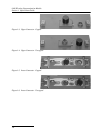
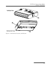
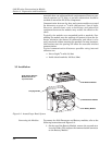
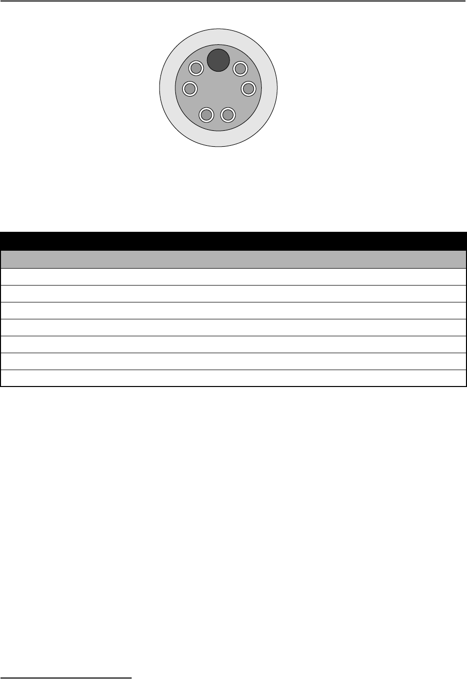
Figure 2-2 2102 Connector Pins
A
B
C
D
E
F
G
Communications Port
(upper connector shown)
Table 2-5 Wireless Module Connector Pins
Pin Name Description
A LONA Neuron differential transceiver Data A
B LONB Neuron differential transceiver Data B
C VIN+ Positive power supply voltage input (+12 VDC nominal)
D VIN– Negative power supply voltage input (0 VDC nominal)
E RCVUP PC data receiver RS-232 level input
F XMTUP PC data transmit RS-232 level output
G Key Aligns connector pins