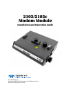
2103 Modem Module
Table of Contents
iv
5.3.2 Reactivating the Desiccant . . . . . . . . . . . . . . . . . . . . . . . . . . . . . . . . . . . . . . 5-2
5.4 Hydrophobic Filter . . . . . . . . . . . . . . . . . . . . . . . . . . . . . . . . . . . . . . . . . . . . . . . . . . 5-3
5.5 O-Rings . . . . . . . . . . . . . . . . . . . . . . . . . . . . . . . . . . . . . . . . . . . . . . . . . . . . . . . . . . . 5-3
5.6 How to Obtain Service . . . . . . . . . . . . . . . . . . . . . . . . . . . . . . . . . . . . . . . . . . . . . . . 5-3
Appendix A Replacement Parts
A.1 Replacement Parts . . . . . . . . . . . . . . . . . . . . . . . . . . . . . . . . . . . . . . . . . . . . . . . . . . A-1
A.1.1 2103 Replacement Parts . . . . . . . . . . . . . . . . . . . . . . . . . . . . . . . . . . . . . . . . A-2
A.1.2 2103c Replacement Parts . . . . . . . . . . . . . . . . . . . . . . . . . . . . . . . . . . . . . . . A-5
Appendix B Accessories
B.1 How to Order. . . . . . . . . . . . . . . . . . . . . . . . . . . . . . . . . . . . . . . . . . . . . . . . . . . . . . . B-1
B.2 General Accessories . . . . . . . . . . . . . . . . . . . . . . . . . . . . . . . . . . . . . . . . . . . . . . . . . B-1
Appendix C Material Safety Data Sheets
C.1 Overview . . . . . . . . . . . . . . . . . . . . . . . . . . . . . . . . . . . . . . . . . . . . . . . . . . . . . . . . . . C-1
List of Figures
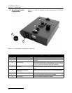
1-1 2103 Modem Components - Top View . . . . . . . . . . . . . . . . . . . . . . . . . . . . . . . . . . . 1-2
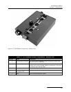
1-2 2103 Modem Components - Bottom View . . . . . . . . . . . . . . . . . . . . . . . . . . . . . . . . 1-3
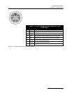
1-3 2103 Communication Connector Pins . . . . . . . . . . . . . . . . . . . . . . . . . . . . . . . . . . . 1-5
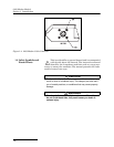
1-4 2103 Modem Cable Connector . . . . . . . . . . . . . . . . . . . . . . . . . . . . . . . . . . . . . . . . . 1-6
2-1 Connecting the Modem Cable . . . . . . . . . . . . . . . . . . . . . . . . . . . . . . . . . . . . . . . . . 2-5
2-2 2103 Modem Cable Connector . . . . . . . . . . . . . . . . . . . . . . . . . . . . . . . . . . . . . . . . . 2-5
2-3 Flowlink Connect Screen . . . . . . . . . . . . . . . . . . . . . . . . . . . . . . . . . . . . . . . . . . . . . 2-6
3-1 2103c magnetic-mount antenna . . . . . . . . . . . . . . . . . . . . . . . . . . . . . . . . . . . . . . . 3-1
3-2 2103c buried antenna . . . . . . . . . . . . . . . . . . . . . . . . . . . . . . . . . . . . . . . . . . . . . . . . 3-2
3-3 Setting dialout phone numbers and alarm conditions . . . . . . . . . . . . . . . . . . . . . . 3-3
3-4 TAP Service Provider Screen . . . . . . . . . . . . . . . . . . . . . . . . . . . . . . . . . . . . . . . . . . 3-3
3-5 TAP Service Parameters . . . . . . . . . . . . . . . . . . . . . . . . . . . . . . . . . . . . . . . . . . . . . 3-4
4-1 Configuration Example (Direct Connection Shown) . . . . . . . . . . . . . . . . . . . . . . . 4-3
List of Tables
1-1 2103 Modem Module Components - Top View . . . . . . . . . . . . . . . . . . . . . . . . . . . . 1-2
1-2 2103 Modem Module Components - Bottom View . . . . . . . . . . . . . . . . . . . . . . . . . 1-3
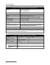
1-3 2103 Modem Module Technical Specifications . . . . . . . . . . . . . . . . . . . . . . . . . . . . 1-4
1-4 Specifications – 2191 Battery Module . . . . . . . . . . . . . . . . . . . . . . . . . . . . . . . . . . . 1-4
1-5 2103 Communication Connector Pins
(2103 only) . . . . . . . . . . . . . . . . . . . . . . . . . . . . . . . . . . . . . . . . . . . . . . . . . . . . . . . . 1-5
4-1 Modbus ASCII Address 1 Register Definitions . . . . . . . . . . . . . . . . . . . . . . . . . . . . 4-6
4-2 Modbus ASCII Address 2-(N+1) Register Definitions . . . . . . . . . . . . . . . . . . . . . . 4-7
4-3 Measurement Parameters by Model Number* . . . . . . . . . . . . . . . . . . . . . . . . . . . . 4-9


