


page 12
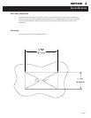
Internal Adjustments
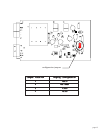
The internal adjustments are factory set and should not be changed. However, if the need arises
and suitable standards are available the following adjustments can be made. (see figure on page 3-4)
Full ScaleFull Scale
Full ScaleFull Scale
Full Scale
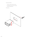
The full scale potentiometer changes the display by changing the sensitivity of the instrument.
Apply a calibrated +5 VDC signal to the
Sig HiSig Hi
Sig HiSig Hi
Sig Hi and
Sig LoSig Lo
Sig LoSig Lo
Sig Lo pins on the back of the power
supply. The display of the instrument should read “100.0”, “10.00” or “1.000”depending upon the
configuration. Adjust the full scale potentiometer (R11) if needed.
Analog OutputAnalog Output
Analog OutputAnalog Output
Analog Output
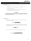
The analog output potentiometer changes the analog output voltage by changing the gain on the
output buffer amplifier. Apply a calibrated pressure standard to the transducer and refer to
equation (1). Adjust the potentiometer (R18) as needed.
Notes on internal adjustments:
* Both the full scale reading and the analog output voltage can change by only ± 10%.
** Zero adjustment can only be performed on the flowmeter itself. Consult your flowmeters
manual for making these adjustments.
Display ConfigurationDisplay Configuration
Display ConfigurationDisplay Configuration
Display Configuration
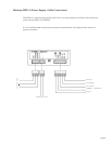
The jumper position on the power supply circuit board determines the location of the decimal on
the display. The jumper is factory set to match the configuration specified by the customer. Should
the need arise to change the display configuration, this jumper can be easily moved (see figure on
page 13).