


25111 Arctic Ocean Drive
Lake Forest, CA 92630
tel. 949.455.4000 fax. 949.455.4010
www.telenetics.com
Specifications*
connector
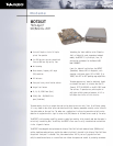
The maximum data rate for this modem is:
▲ 0 to 1200 bps (baud) over ITU M.1025 or
BELL 3002 Basic services.
▲ 0 to 1800 bps (baud) over ITU M.1020 or
BELL 3002 C2 conditioned lines.
Interface Compatibility
▲ The modem’s line interface is compatible
with the Bell Systems/WE 202 specifications
and with the ITU V.23 recommendation.
▲ The modem’s data interface is compatible
with the RS 232C specifications and with
the ITU V.24/28 recommendations.
Document #0071 0700
Telenetics is registered trademark of Telenetics Corporation.
All other trademarks are the property of their respective holders. ©2000
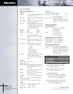
FUNCTIONAL DESCRIPTION
General
Data Rate From 0 to 1800 bps (baud) depending
on transmission facility
Modulation Phase-coherent Frequency shift keying
(FSK).
Line Impedance 600 ohms ± 10 %, transformer coupled
and transient protected
Operation The modem operates at full duplex or
half duplex over four-wire lines, or
half-duplex only over two-wire lines.
It operates asynchronously.
Receive and Space: 2200 Hz
Transmit
Mark: 1200 Hz
Frequencies
Soft carrier: 900 Hz
Timings All settings and timings are
controlled by jumpers on the modem
board.
Anti-streaming Option to turn transmitter OFF after a
selected time, even if Request To Send
is ON
Test Features The modem employs a rotary switch
that selects these test options:
• Data Mode
• Self Test
• Analog Loop back
• Digital Loop back
• Test Pattern Transmit
Indicators The modem has LED indicators for the
following interface circuits:
RTS, CTS, DCD, RD, TD, TM (Test Mode)
and PWR.
Receiver
Receiver Center 1700Hz ± 16 Hz
Frequency Tolerance
Receiver Performance The modem receiver will operate with
the following performance at 3002/C2 or
M1025 lines
1200Bps: B.E.R. equal to 1 x 10
-5
with 12 db
signal to noise ratio
1800Bps: B.E.R. equal to 1 x 10
-5
with 18 db
signal to noise ratio
Carrier Detect The received carrier detect threshold can
Threshold
be configured by the on-board jumper.
With jumper option:
DCD off ➞ on Carrier stronger than –30 dBm
OORR
DCD off ➞ on Carrier stronger than –45 dBm
Hysteresis: Approximately 2 dB
Receiver Dynamic 0 dBm to – 43 dBm
Range
Transmitter
Transmit FrequencySpace frequency: ± 0.1 %
Tolerances
Mark frequency: ± 0.1 %
Soft Carrier frequency: ± 0.1 %
Transmit Levels The modem transmit level is
selectable from 0 dBm to – 14 dBm in
2 dB steps by the on-board jumper S2-
1 to 8.
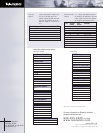
POWER REQUIREMENTS
Rack & Standalone
AC Power 20 VAC RMS @ 150 mA, centertapped.
10 VAC RMS @ 225 mA.
115VAC & 220/240VAC
DC Power +15 VDC referred to gnd
-15 VDC referred to gnd.
+8.5 VDC referred to gnd.
ENVIRONMENTAL SPECIFICATIONS
Operating Temperature -40 to + 85 degrees C
Storage Temperature -40 to + 85 degrees C
Relative Humidity 95%, non-condensing
INTERFACE SPECIFICATIONS
Analog Line edge An 8-pin edge connector located at
the backend of the modem board. The
four signals routed to and from this
connector are the analog transmit and
receive pairs. Each pair are fully
differential signals.
Pin Signal Name Function
3 DTR Receive Line for four wire systems
4 DTX Transmit/Receive Line for two wire systems
5 DRX Transmit/Receive Line for two wire systems
6 DRR Receive Line for four wire systems