


Configuring the Modem
Page
11
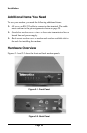
On the front panel of the modem, there are:
c
One Power LED and six status LEDs (see page 21)
c
A rotary test switch (see page 22)
On the back panel of the MOT202TSA modem, there are:
c
A power cord or power input connector
c
A power switch for turning the modem on and off
c
A fuse, 3/8 amp, 250 Volt, slow-blow
c
A DB25 female connector for accommodating a DTE device
c
An RJ-45 connector for connecting to a communications line
Configuring the Modem
The modem obtains some operating characteristics from jumper
settings. The default jumper settings are for common 4-wire full-duplex
applications. To reconfigure the modem for 2-wire half-duplex and
special applications, you must change the default jumper settings.
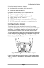
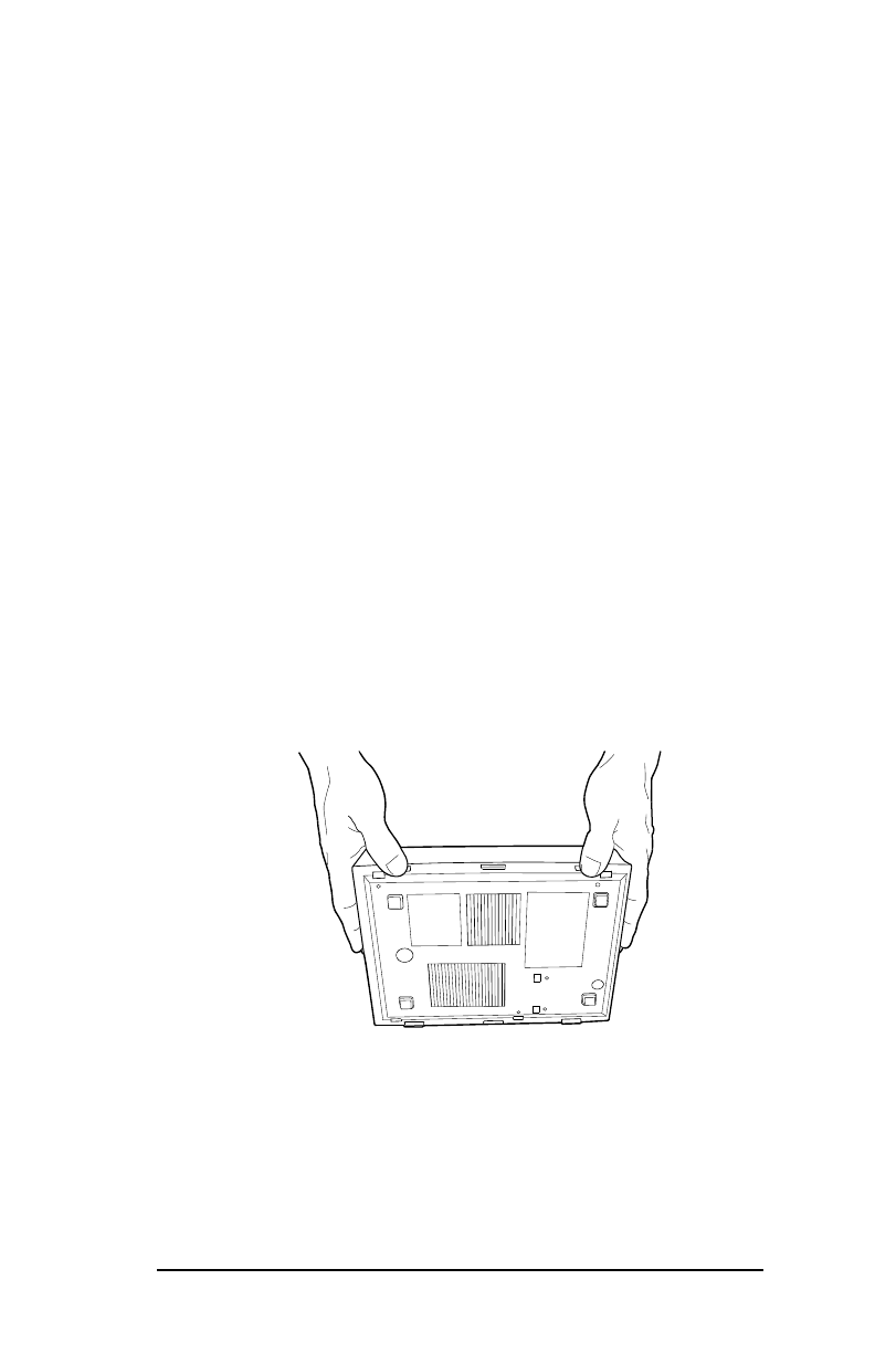
To change jumper settings, push the two tabs on the back of the modem
to open the modem cover and gain access to the jumper settings on the
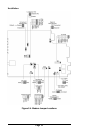
printed circuit board (see Figure 2-3). Then set the jumpers to the
desired settings and replace the cover.
Figure 2-3. Gaining Access to the Modem Jumpers
Figure 2-4 on the next page shows the location of the modem jumpers.
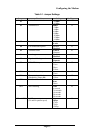
Table 2-1 on page 13 summarizes the jumper settings (default settings
are
bold
).