


Operation 9
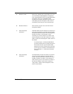
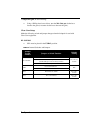
Connector Pin Configurations
Headset Connector
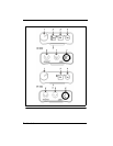
Type: XLR-4M (callout in Figure 1)
Pin 1 Headset Microphone Low
Pin 2 Headset Microphone High
Pin 3 Headphone High
Pin 4 Headphone Low
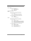
Intercom Channel Connectors
BP-1002
Type: One XLR-3M and XLR-3F pair (callout 8 in Figure 1)
Audiocom
®
Mode (Internal switch SW1 set to BAL position)
Pin 1 Common
Pin 2 Intercom audio/call low and +24VDC input
Pin 3 Intercom audio/call high and +24VDC input
Clear-Com
®
Mode (Internal switch SW1 set to UNBAL position)
Pin 1 Common
Pin 2 +30VDC input
Pin 3 Intercom audio/call signal
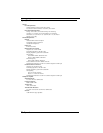
BP-2002
Type: One XLR-6M and XLR-6F pair (callout 7 in Figure 1)
Audiocom
®
Mode (Internal switch SW1 set to BAL position)
Pin 1 Common
Pin 2 Local Power (21-30VDC)
Pin 3 Channel A intercom audio/call low and +24VDC input
Pin 4 Channel A intercom audio/call high and +24VDC input
Pin 5 Channel B intercom audio/call low and +24VDC input
Pin 6 Channel B intercom audio/call high and +24VDC input
Clear-Com
®
Mode (Internal switch SW1 set to UNBAL position)
Pin 1 Common
Pin 2 Local Power (21-30VDC)
Pin 3 Channel A +30 VDC input
Pin 4 Channel A intercom audio/call signal
Pin 5 Channel B +30VDC input
Pin 6 Channel B intercom audio/call signal