


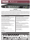
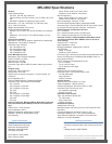

MS-4002 Specications
General
Power Requirements:
AC Input: 100-240 VAC, 50/60 Hz
Channel Power: 24 VDC nominal (12 to 30 VDC), 65 to 150
mA
MS-4002 is capable of supplying 4 amps overall
Dimensions: 1.75” (44.5 mm) high, 19” (483 mm) wide,
10.31” (261.9 mm) deep
Weight: approximately 4.5 lb (2 kg)
Environmental Requirements:
Storage: -20°C to 80°C; 0% to 95% humidity, non-condens-
ing
Operating: -15°C to 60°C; 0% to 95% humidity, non-con-
densing
Dynamic-mic Headset
Microphone: 50 to 200 Ω, dynamic (balanced or unbalanced)
Headphones: 150 to 600 Ω, monaural
Connector Type: XLR-4M
Pin 1 Microphone low
Pin 2 Microphone high
Pin 3 Headphone high
Pin 4 Headphone low
Panel Microphone Input
Microphone Type: Electret condenser
Power: Phantom (+5 VDC)
Nominal Level: -42 dBu
Maximum Level: -25 dBu
Connector Type: IKP12 (MCP-90 series, stereo plug connec-
tor)
Program Input
Input Level: 100mV maximum
Voltage Gain: 25 ±3 dB
Output Level (to intercom channel) :1.0 Vrms nominal, 2.3
Vrms max.
Input Impedance: 75 k
Common Mode Rejection: Greater than 50 dB
Connector Type: 9-pin female D-sub (DE9S)
Pin 1 Ground
Pin 2 Program 1 input low
Pin 3 Program 2 input low
Pin 4 NC
Pin 5 NC
Pin 6 Program 1 input high
Pin 7 Program 2 input high
Pin 8 NC
Pin 9 NC
Intercom Channels, Balanced Mode (Both Back Panel and
internal switches (BAL/UNBAL) must be set to same set-
ting)
Output Level: 1 Vrms nominal
Input Impedance: 300 Ω
Bridging Impedance: greater than 10,000 Ω
Sidetone: -40 dB, 35 dB adjustable range
Call Signaling:
Send: 20 kHz ±100 Hz, 0.5 Vrms ±10%
Receive: 20 kHz ±800 Hz, 100 mVrms
Mic-Kill Frequency:
Send: 24 kHz ±300 Hz, 0.5 Vrms ±10%
Detect: 24 kHz ±800 Hz, 100 mVrms
Noise Contribution: less than -70 dB
Common Mode Rejection Ratio: greater than 50 dB
Connector Type: One XLR-3M and XLR-3F pair, wired in paral-
lel, for each channel (permits “loop-thru” connection).
XLR-3 Balanced Conguration Pinouts
Pin 1: Common
Pin 2: Intercom audio low and +24 VDC input
Pin 3: Intercom audio high and +24 VDC input
Intercom Channel, Unbalanced Mode (Both Back Panel
and internal switches (BAL/ UNBAL) have to be set to
same setting)
Output Level: 1 Vrms ±10%
Input Impedance: 150 Ω
Bridging Impedance: greater than 10,000 Ω
Call Signaling:
Send: 11 ±3 VDC
Receive: 4 VDC minimum
Connector Type: Uses same connectors as for balanced mode,
above, but with pinouts modied by BAL/UNBAL switch on
back panel as follows:
XLR-3 Unbalanced Conguration Pinouts
Pin 1: Common
Pin 2: +24 VDC input
Pin 3: Intercom audio high
PA Output
Output Level: 235 mVrms nominal
Connector Type: ⅛-inch Stereo Phone Jack
Tip: PA output high
Ring: Not used
Sleeve: Common
Speaker Output
Output Level: 0 dB nominal (1.0 Vrms)
Output Impedance: 1000 Ω nominal
Frequency Response: 200 Hz to 8 kHz +1/-3dB
Connector Type: RCA Phono Jack
Tip: Speaker output high
Sleeve: Common
Expansion Input /Output
Type: 2.0 mm stereo phone jack
Tip: Talk output
Ring: Listen input
Sleeve: Common
Headphone Amplier
Voltage Gain: 30 ±3 dB
Maximum Output: 250 mW ±10% into 150 Ω, 65 mW ±10%
into 600 Ω
Frequency Response: 200 Hz to 8 kHz +1/-3db
Incoming Call Beep Tone: 2 kHz, at the headphones
Total Harmonic Distortion: Less than 0.2% at 200 mW
Sidetone: 18 ±2 dB, adjustable
Ordering Information
MS-4002
4 channel user/main station with 4.0 amp power sup-
ply
Catalog Number: 90007799000
This specications information is preliminary and is subject to change without notication.
Brand names mentioned are the property of their respective companies.
Contact Information
Telex Communications, Inc.
12000 Portland Avenue South
Burnsville, Minnesota 55337
Telephone: (800) 392-0498
Fax: (800) 323-0498
Form Number: 38110-426B
Date: February, 2006