


UC864-E Hardware User Guide
1vv0300766a Rev.1 - 31/01/08
Reproduction forbidden without Telit Communications S.p.A. written authorization - All Rights Reserved page 43 of 51
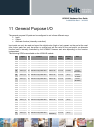
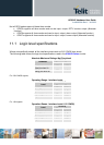
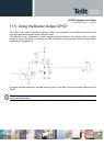
11.2 Using a GPIO Pad as INPUT
The GPIO pads, when used as inputs, can be connected to a digital output of another device and
report its status, provided this device has interface levels compatible with the 2.6V CMOS levels of the
GPIO.
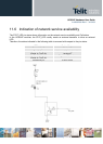
NOTE: If the digital output of the device to be connected with the GPIO input pad has interface levels
different from the 2.6V CMOS, it can be buffered with an open collector transistor, provided a 47KΩ
pull-up resistor is connected as seen in the paragraph 0
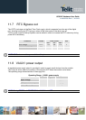
11.3 Using a GPIO Pad as OUTPUT
The GPIO pads, when used as outputs, can drive 2.6V CMOS digital devices or compatible hardware.
When set as outputs, the pads have a push-pull output and therefore the pull-up resistor may be
omitted.
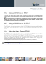
11.4 Using the Alarm Output GPIO6
The GPIO6 pad, when configured as Alarm Output, is controlled by the UC864-E module and will rise
when the alarm starts and fall after the issue of a dedicated AT command.
This output can be used to power up the UC864-E controlling microcontroller or application at the
alarm time, giving you the possibility to program a timely system wake-up to achieve some periodic
actions and completely turn off either the application and the UC864-E during sleep periods,
dramatically reducing the sleep consumption to few μA.
In battery-powered devices this feature will greatly improve the autonomy of the device.
NOTE: During RESET the line is set to HIGH logic level.