


Laser Radiation
Avoid Exposure to Beam
Laser Class 1 Product
Complies with 21 CFR
1.
8.
9.
10.
11.
12.
13.
14.
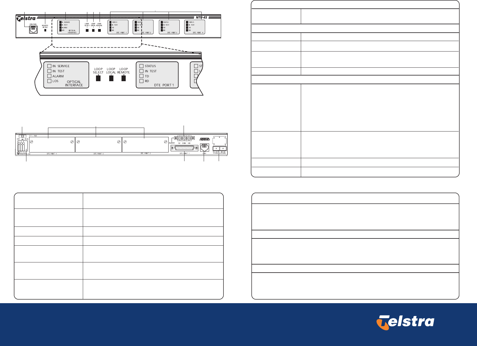
Local Control Port
(Telstra use only)
VT100, EIA-232 Interface for local management
4. Loop Select
5. Loop Local
6. Loop Remote
48V DC power interface (Earth, Positive, Negative)
Slots to accomodate optional HSSI or V.35 DTE modules
The Loop Select button is used to select the port that is to be looped. It will cycle through
the four ports, causing the respective ports Test LED to flash.
When a loop is in place, pressing this button will turn the loop off.
When a port has been selected using the Loop Select button, pressing the Loop Local
button will initiate a loop on the selected port of the local NTU-45.
When a loop is in place, pressing this button will turn the loop off.
When a port has been selected using the Loop Select button, pressing the Loop Remote button
will initiate a loop on the selected port of the remote NTU-45.
When a loop is in place, pressing this button will turn the loop off.
In-built High Speed Serial Interface (HSSI)
Alarm Relay Contacts (Normally Closed, Common, Normally Open)
10BaseT LAN interface for remote management via MACS
Flat-SC Optical interface with separate Transmit and Receive fibres
Power Cord Strain Relief
TDC Power erminal Block
DTE Ports 2, 3 and 4
DTE Port 1
Alarm Port
(Telstra use only)
Management Port
(Telstra use only)
Optical Interface Port
(Telstra use only)
Interfaces
NTU-45 Rear Panel
NTU-45 Front Panel
Front Panel Push Buttons
Front Panel LEDs
7. DTE Port LEDs (Customer Interfaces)
3. Optical Interface LEDs (Network Interface - Telstra Use Only)
Status (Green
Yellow or Red)
OFF indicates that there is no card installed
Flashing GREEN indicates that the interface is not configured for service
GREEN indicates that the interface is ready to carry data.
YELLOW indicates that the interface is ready, but cannot detect the
customer's equipment (DTE)
RED indicates that there is a problem with the interface.
IN SERVICE (Green)
Indicates when the NTU-45 is powered on and functioning correctly.
2. Remote Active LED (Telstra use only)
Remote Active
(Yellow)
Indicates when the NTU-45 is being managed locally, or via a Telnet session
TEST (Yellow)
Indicates when a Loop or Bit Error Rate test is active on the Optical Interface.
ALARM (Yellow or
Red)
YELLOW indicates that there is a problem with the Remote NTU-45.
LOS (Red)
Indicates that the NTU-45 cannot detect any signal on the Optical Interface.
RED indicates that the NTU-45 cannot align with the incoming signal.
In Test (Yellow)
Indicates when a Loop or Bit Error Rate test is active on the Interface.
During the process of activating a loop from the front panel push buttons,
this LED will Flash, indicating that it is selected but no Loop test exists.
TD (Green)
Indicates that the interface is transmitting data to the Newtork
RD (Green)
Indicates that the interface is receiving data from the Network
1
108
9
12
11 13 14
23456 7