


www.ti.com
f
IN
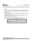
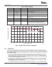
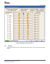
− Input Frequency − MHz
SNR − Signal-to-Noise Ratio − dBFS
G001
9.97 19.94 30.13 40.33 50.13 60.13 69.59 79.87 89.75 100.33 130.13 170.13
68
69
70
71
72
73
74
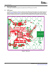
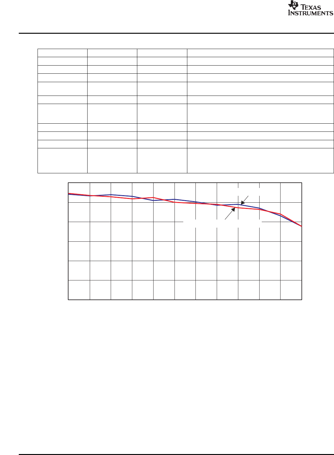
1 Decoupling Cap
Baseline-All Decoupling Caps
3.2.3AnalogInputs
CircuitDescription
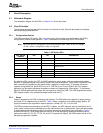
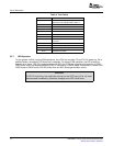
Table2.EVMPowerOptions
BANANAJACKNAMEVOLTAGEDESCRIPTION
J9DeviceAGNDGND
J10AGNDGND
J11DeviceAVDD3.3Deviceanalogsupply
J12Amplifiernegative–5THS4509Vs–supply
rail
J13Amplifierpositiverail5THS4509Vs+supply
J14Auxiliarypower5SuppliespowertoallperipheralcircuitryincludingtheFPGA
andPROM.VoltagesrailsarecreatedbyusingTI'sTPS75003
voltageregulator.
J15DeviceDVDD3.3Deviceinternaldigitaloutputsupply
J16DGNDGND
J17DGNDGND
J20IfTP11,TP12,andTP13aretiedlow,theTPS75003is
disabled.Inthiscase,onecansupply3.3Vtopin1,1.2Vto
pin2,and2.2Vtopin3ofJ20whileconnectingthegroundto
J17.
Figure1.ADS5547SNRPerformancevsDecoupling
TheEVMcanbeconfiguredtoprovidetheADCwitheithertransformer-coupledordifferentialamplifier
inputsfromasingle-endedsource.TheinputsareprovidedviaSMAconnectorJ3fortransformer-coupled
inputorSMAconnectorJ1fordifferentialamplifierinput.Tosetupforoneoftheseoptions,theEVMmust
beconfiguredasfollows:
1.Fora1:1transformer-coupledinputtotheADC,asingle-endedsourceisconnectedtoJ3.Confirm
thatSJP4haspins2and3shorted,andthatSJP5haspins2and3shorted.Thetransformerused,
theMini-CircuitsTC4-1W,formsaninherentband-passfilterwithapassbandfrom3MHzto800MHz.
ThisisthedefaultconfigurationfortheEVM.
2.OnecanuseaTITHS4509amplifiertodrivetheADCbyapplyinganinputtoJ1.ReconfigureSJP4
andSJP5suchthatbothhavepins1and2shorted.A5-VDCsupplymustbeconnectedtotheboard
toprovidepowertoU3forthisconfiguration.
TheTHS4509amplifierpathconvertsasingle-endedsignalpresentedonJ1intoadifferentialsignal.
8SLWU028B–January2006–RevisedNovember2006
SubmitDocumentationFeedback