


www.ti.com
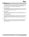
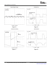
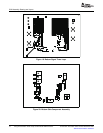
t − Time − 1 µs/div
V
IN
= 36 V
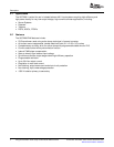
6.3 V, QF Gate (J5)
(5 V/div)
8.4 V, QR Gate (J6)
(5 V/div)
SR Gate Drive
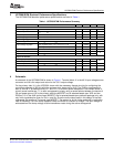
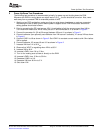
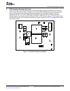
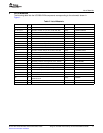
t − Time − 2.5 µs/div
V
IN
= 36 V
I
OUT
= 30 A
50 mV/div
23 mV peak-to-peak
Output Ripple Voltage
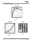
t − Time − 1 µs/div
V
IN
= 72 V
12.3 V, QF Gate (J5)
(5 V/div)
5.4 V, QR Gate (J6)
(5 V/div)
SR Gate Drive
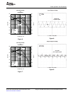
t − Time − 2.5 µs/div
V
IN
= 48 V
I
OUT
= 10 A
V
PRI
(40 V/div)
I
PRI
(0.5 A/div)
Transformer Primary
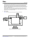
PowerUp/DownTestProcedures
Figure12.
Figure10.
Figure13.
Figure11.
12UsingtheUCC2891ActiveClampCurrentModePWMControllerSLUU178A–November2003–RevisedDecember2006
SubmitDocumentationFeedback