


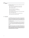

Description
1-3
General Information
1.3 Operating Guidelines
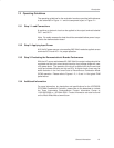
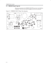
The operating guidelines for the evaluation board are provided with reference
to the schematic in Figure 1−1 and the component layout in Figure 2−1.
1.3.1 Step 1. Load Connections
A resistive or electronic load can be applied to the output terminals labeled
OUT− and OUT+.
Note: For safety reasons the load should be connected before power is sup-
plied to the demonstration board.
1.3.2 Step 2. Applying Input Power
A 60 Hz AC power source not exceeding 265 V
RMS
needs be applied across
terminals AC−N and AC−L for proper operation.
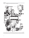
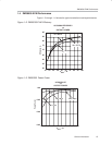
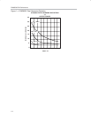
1.3.3 Step 3. Evaluating the Demonstration’s Boards Performance.
With the AC source set between 85−265 V
RMS
the output voltage should be
regulated and the input current should track the input voltage shape with near
unity power factor. The operation of the circuit is verified over the line and load
range and shows efficiency as high as 85%. At lighter loads, there may be
some distortion in the line current due to Discontinuous Conduction Mode
(DCM) operation. Please refer to Figures 1−2, 1−3 and 1−4 for typical EVM
performance.
1.3.4 Additional Information
For more information, pin description and specifications for the UCC38500
PFC/PWM Combination Controller, please refer to the datasheet or contact
the Texas Instruments Semiconductor Product Information Center at
1-800-336-5236 or 1-972-644-5580. Product Information can also be found
on the World Wide Web at www.ti.com.