


Jumpers and Test Points
3-3
EVM Operation
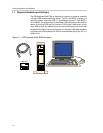
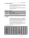
3.5 Jumpers and Test Points
Table 3–2 describes the jumpers, J1 and J2, used to connect P3.0 and P3.1
to D6 and D7 respectively, which should only be done when P3.0/S0 and
P3.1/S1 are not set to GND for VID/PID selection (see the TUSB2136
keyboard hub controller data sheet).
Table 3–2 also describes the various 0-Ω resistors used as jumpers. Test
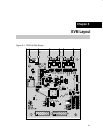
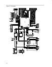
points are located throughout the EVM. For location of these test points,
consult the layout in Section 5.
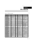
Table 3–2.Jumpers and Test Points
Jumpers Description
J1 Installed: connects P3.1 to D7
J2 Installed: connects P3.0 to D6
R30 thru R35
0-Ω resistors used to configure the TUSB2136. For proper operation with the firmware and
EVM, R30, R31, and R33 are installed at the factory.
R29, R36, R37, R38 0-Ω resistors on power lines which may be removed to insert a current meter.
3.6 EEPROM
The EEPROM is used for application-specific firmware. The TUSB2136 will
automatically read the EEPROM at power up via the I
2
C bus. A header must
be added to the application firmware before loading into the EEPROM. This
header format is specified in the bootcode document provided with the
TUSB2136. The header may be generated automatically with the I
2
C header
generation utility software also provided with the TUSB2136.
For convenience, the EEPROM has been installed on a socket. If desired, the
socket may be removed and the EEPROM can be soldered directly onto the
board. Using J3 and J4, the firmware installed at the factory will support a
QWERTY keyboard with the matrix shown in Table 3–3.
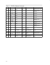
Table 3–3.QWERTY Keyboard Matrix
Port
No.
Matrix
P3.6
COL 1
P0.6
COL 2
P0.7
COL 3
P0.4
COL 4
P0.5
COL 5
P0.2
COL 6
P0.3
COL 7
P0.0
COL 8
P0.1
COL 9
P1.6
COL 10
P2.7 ROW 1 Q 9 A 6 Z 3 DEL
P2.6 ROW 2 W 8 S 5 X 2 0
P2.5 ROW 3 E 7 D 4 C 1 INS
P2.4 ROW 4 R ESC F HOME V END R ARROW
P2.3 ROW 5 T I G K B / SPACE
P2.2 ROW 6 Y P H “ N U ARROW D ARROW
P2.1 ROW 7 U O J L M \ L ARROW
P2.0 ROW 8 – , + ENTER . SHIFT ALT CTL