


Printed Circuit Board (PCB) Layout
4
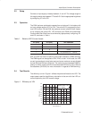
3 Printed Circuit Board (PCB) Layout
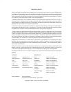
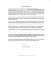
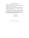
PCB layout is critical for all switch-mode power supplies. Figure 2, Figure 3,
and Figure 4 show the board layout for the TPS60230EVM-047 PWB. The
nodes with high switching frequencies and currents are short and are isolated
from the noise-sensitive feedback circuitry. Careful attention has been given
to the routing of high-frequency current loops. Refer to the product datasheet
(SLVS516) for specific layout guidelines.
Figure 2. Assembly Layer
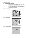
Figure 3. Top Layer Routing
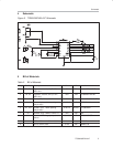
Figure 4. Bottom Layer Routing