


Jumpers and Test Points
3-3
EVM Operation
3.5 Jumpers and Test Points
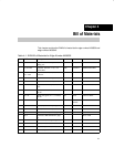
Table 3–2 describes the jumpers J1 and J2, used to connect P3.0 and P3.1
to D6 and D7 respectively, which should only be done when P3.0/S0 and
P3.1/S1 are not set to GND for VID/PID selection (see the TUSB2136
keyboard hub controller data sheet, literature number SLLS442) via SW1–3
and SW1–4.
Table 3–2 also describes the various 0-Ω resistors used as jumpers. Test
points are located throughout the EVM. For location of these test points, see
the EVM Layout section of this user’s guide.
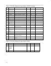
Table 3–2.Jumpers and Test Points
Jumpers Description
J1 Connects P3.1 to D7
J2 Connects P3.0 to D6
J9 Connects the serial data line of the EEPROM to the TUSB2136. Installed at factory.
J10 Connects power to the RS232 interface chip
J11, J12 Connects the transmit and receive lines on the RS232 interface chip to the TUSB2136
SW1
A set of six switches used to configure the TUSB2136. For proper operation with the
firmware and EVM, SW1–3, SW1–5, and SW1–6 should be set to on.
R29, R36, R37, R38 0-Ω resistors on power lines which may be removed to insert a current meter
3.6 EEPROM
The EEPROM is used for application-specific firmware. The TUSB2136
automatically reads the EEPROM at power up via the I
2
C bus. A header must
be added to the application firmware before loading into the EEPROM. This
header format is specified in the bootcode document (literature number
SLLU025), which can be found on the EVM web page at
www.ti.com/sc/usb–kbdkit. The header may be generated automatically with
the I
2
C header generation utility software also found on the EVM website
For convenience, the EEPROM has been installed on a socket. If desired, the
socket may be removed and the EEPROM can be soldered directly onto the
board. The firmware installed at the factory supports the miniature QWERTY
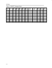
keyboard with the matrix shown in Table 3–3. The miniature QWERTY
keyboard connects to J3 and J4.