


3
____________________________
____________________________
____________________________
____________________________
____________________________
____________________________
____________________________
____________________________
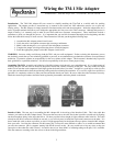
Mic Adapter RJ-11 Mic Adapter RJ-45 / 8-Pin Rnd
Jumper Wire Diagram
Ground (Pwr)
Acc. Voltage
PTT
RX Audio
Ground (Mic)
TX Audio
A
Speaker Input
B
C
D
E
F
SQ
1
2
3
4
5
6
7
8
____________________________
____________________________
____________________________
____________________________
____________________________
____________________________
____________________________
____________________________
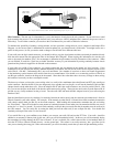
Mic Adapter RJ-11 Mic Adapter RJ-45 / 8-Pin Rnd
Jumper Wire Diagram
Ground (Pwr)
Acc. Voltage
PTT
RX Audio
Ground (Mic)
TX Audio
A
Speaker Input
B
C
D
E
F
SQ
1
2
3
4
5
6
7
8
Once you have established whether or
not the pins in the manual are listed in
reverse order, you should enter the
signal names into the appropriate lines
of the Jumper Wire Diagram. If the
lines were not reversed, then you can
enter the signals exactly as they are
numbered in your radio manual. If the
connector numbers were reversed, then
enter the signals into Jumper Wire
Diagram in the reverse order. This
means that the signal listed in the radio
manual as Pin #8 should be entered into
the Jumper Wire Diagram next to Pin
#1. The signal listed in the manual as
Pin #7 should be entered into the
Jumper Wire Diagram as Pin #2 and so
on, until all entries are complete.
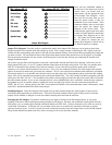
Jumper Wire Diagram: Now that you have completed the entries in the Jumper Wire Diagram, you are ready to draw in the
Jumpers that need to be installed on the Mic Adapter pc board. This is simply a matter of matching the TM-1 signals in the left
column with the corresponding radio signals in the right column and then drawing a line between them representing the jumper that
you need to install. You may find that some of the signal names taken from the radio manual are not as descriptive as you might
like, but generally the manual will also contain a brief description of each line that will help you understand the function well
enough to make the match.
On occasion you may find a radio that does not provide a separate Mic Ground and Chassis (Pwr) Ground. In this case you can
simply jumper TM-1 pins “A” and “F” together and then connect them to the single radio ground. The TM-1 uses speaker audio
(Pin “D”) to determine if the channel is busy before it transmits. If your radio does not provide speaker audio on the mic
connector, you can deal with the problem in several ways. First, if you are technically inclined, you could run the radios speaker
audio to an unused (or unnecessary) pin on the mic connector. This is a nice solution but sometimes rather difficult to accomplish.
The second solution is to run speaker audio from the radios Aux Spkr jack to the 3.5mm miniature phone jack on the Mic Adapter
board. This jack is connected to the terminal point on the board marked “SQ”. The “SQ” terminal can then be jumpered to the RX
Audio pin to the TM-1 (Pin “D”). The drawback to this solution is that plugging into the Aux Spkr jack of most radios will disable
the radios internal speaker. If you are also using the radio for voice communications, this is a problem. About the only solution to
that problem is to use an external speaker or modify the radios Aux Spkr jack so that it does not cut the internal speaker off.
NOTE: Pin “B” (Acc. Voltage) going to the TM-1 is not required and should not be connected under normal circumstances. Refer
to the TM-1 Installation Manual for details about this pin.
Installing Jumpers: Using short lengths of the hookup wire provided with the adapter kit, install jumpers on the pc board
according to the diagram that you created above. These wires should be installed on the top side of the pc board, so that the
jumpers can be checked or changed at a later date without removing the board from the enclosure.
Packaging the Mic Adapter: Tigertronics currently does not supply a housing for the Mic Adapter board. It is up to the
ingenuity of the user to find an appropriate package suitable for his purpose. For those who would like to package the board in a
small plastic case, we would suggest looking at the Radio Shack case #270-1801. We have found this case to work very well for
“under dash” installations. To use this case, you will need to drill down or cut off the four standoffs on the floor to provide
clearance for the pc board. You will of course also need to make the necessary holes and cutouts in the case for the Mic Adapter.
The pc board should be mounted to the floor of the case using two #4 screws and short standoffs.
(C) 1999 Tigertronics Rev. 10/10/05