


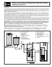
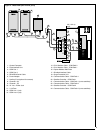
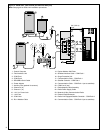
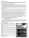
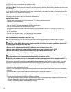
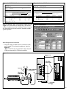
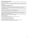
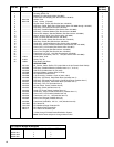

Note: The Motorola radio service software screens shown in
Figure 12, 13, and 14 are for example only. Later service
software versions may not be formatted as shown, however,
the items within boxes must be set as indicated to enable
system operation.
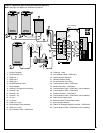
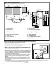
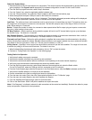
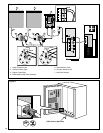
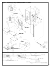
Radio Components Connection
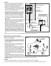
1. Using the cables provided in the kit, connect the radio,
power supply, FIU and central computer as shown in
Figure 15.
Note: FIU CH #3 may be connected to other computer
COM ports depending on COM port availability.
MOTOROLA
Radio Service Software
MaxTrac 300
Version RO5.30.00
Model: D34MJA77A3_K
Serial: 428AUC0648
Software: 008
Coded Squelch
UHF
X W
RANGE/VIEW:RADIO WIDE:CONN CON SCREEN PRINT UTILITY
ACCESSORY CONNECTOR CONFIGURATION
INTERNAL ACCESSORY:NONE EXTERNAL ACCESSORY:PUBLIC ADDRESS CUSTOM:YES
PIN
NUMBER
4
6
8
9
12
14
FUNCTION
# DESCRIPTION
07 CSQ Detect
00 NULL
05 PL/DPL & CSQ Det
02 Emergency Switch
00 NULL
04 PA Switch
DATA
DIRECTION
OUTPUT
INPUT
OUTPUT
INPUT
INPUT
INPUT
DEBOUNCE
NO
NO
NO
YES
NO
YES
ACTIVE
LEVEL
HIGH
LOW
HIGH
HIGH
LOW
LOW
POWER-UP DELAY: 0.187 SEC
15 Feb 95
21:23
MOTOROLA
Radio Service Software
Radius SM50 Version RO1.00.00
Model: M34DGC20A2__
Serial: PATSNBASIC
Coded Squelch
X W UHF Band
CHANGE/VIEW:RADIO WIDE:ACCESSORY
ACCESSORY CONFIGURATION
PIN
ACC. External......General I/O
ACC. Rx Audio......Unmuted
Power-Up Delay......2.5
ACC. Custom.........Y
4
8
9
12
14
FUNCTION
CSQ Detect
PL/DPL & CSQ Det
NULL
NULL
External PTT
DIRECTION
OUTPUT
OUTPUT
INPUT
INPUT
INPUT
DEBOUNCE
N
N
N
N
Y
ACT LEVEL
03 Sep 96
16:00
HIGH
HIGH
LOW
LOW
LOW
Figure 12 - MAXTRAC 300 Radio
Figure 13 – Radius SM50 Radio
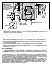
Figure 15
FIU Power
Supply
DB-9/DB-9
Serial Cable
Cable Assembly
P/N 89-7610
Antenna
Motorola
2-Way Radio
Radio Power Supply
Figure 14 – M1225 Radio
10
50' (15.2 m)
max.