


Installing the Field Interface Unit, Wall Plate Assembly and Surge Protection Unit
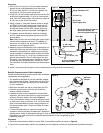
1. Position the Field Interface Unit within 6' (1.8 m) of the PC.
Note: Maximum distance is 50' (15.2 m).
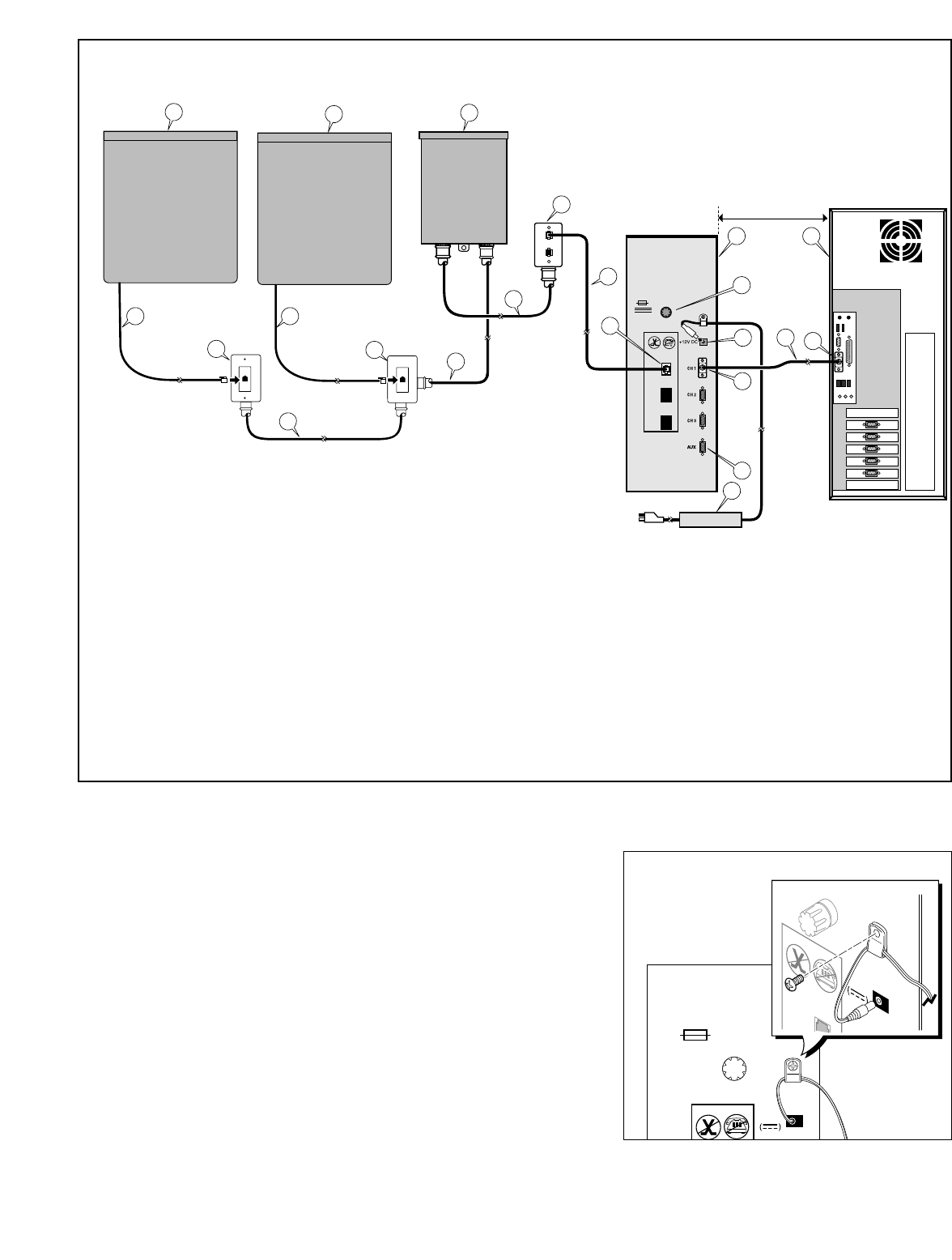
2. Using the serial cable(s) supplied, connect the PC to the FIU as illustrated
in the appropriate configuration diagram
Figure 1–5.
3.
Note: The methods of cable connection will vary depending on the avail-
ability of computer COM ports. DO NOT USE P0 FOR CONNECTION. P0
is recommended for an external modem.
4. With the power switch in the Off position, plug the power adapter into the
FIU 12 V d.c. receptacle and the wall socket outlet using the appropriate
AC power cord supplied. Leave the FIU power switch in the Off position
until the installation has been completed.
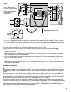
5. To prevent the power wire from being accidentally pulled out, install the
power wire through the strain relief and tighten securely as shown in
Figure 6.
Note: Regulatory agencies specify that when connecting plug-in equip-
ment, the socket-outlet shall be located near the equipment and shall be
easily accessible.
6. To facilitate installation of the modular wall plate, install a standard duplex junction box to the wall within 5' (1.5 m) of the
FIU. The RJ11 modular cable(s) provided are 6' (1.8 m) in length.
(continued)
5
15
15
16
18
18
17
17
16
5
6
11
7
8
9
12
13
14
10
12
3
4
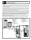
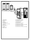
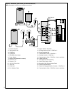
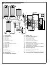
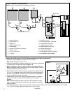
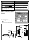
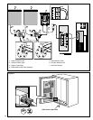
1 - Central Computer
2 - Field Interface Unit
3 - COM Port 1
4 - DB-9/DB-9 Serial Cable
5 - Power Adapter
6 - Auxiliary Port (optional for sensors)
7 - Channel 1 (in)
8 - 12 V d.c. Power Jack
9 - 1.5A Fuse
10 - COM Line 1 (out)
11 - RJ11 Modular Cable - COM Path 1
12 - Duplex Modular Wall Plate
13 - Shielded Interface Cable
14 - Surge Protection Unit (SPU)
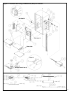
15 - Decoder Interface Unit
16 - Communication Cable
17 - RJ45 Modular Wall Plate Assembly
18 - RJ45 Modular Cable Assembly
+12V DC
L1
L1
+12V DC
Figure 6
Figure 5
- Model 2010 (one wireline port)
Note:
See page 12 for Network CDS installation procedures.
50' (15.2 m)
max.