


TOSHIBA
5.0 Operating the UPS
5.1 Operation Modes
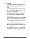
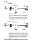
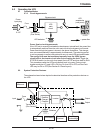
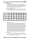
5.1.3 Circuit-bypass mode
Power flow in circuit-bypass mode.
If the UPS unit is severely overloaded or develops an internal fault, the power flow
is automatically switched from the unit's main circuit to the bypass circuit mode.
Power flow through the bypass is shown in the above illustrations. This change-
over occurs automatically in approximately 4 milliseconds. The switching period
is not long enough to cause interruptions to occur in most UPS equipment loads.
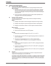
The energy flow must be transferred manually from the UPS's bypass
circuit back to the inverter circuit after first correcting the fault. Toggle the
STOP/RUN switch (on the unit's front panel) first to STOP and then back to RUN.
This procedure resets the UPS and transfers back to inverter. During circuit-
bypass mode the AC-Input LED is ON, the On-Line LED is OFF, and the Fault
LED may be ON or OFF.(See Section 9.2 Panel Layout).
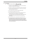
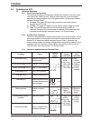
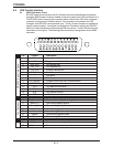
5.2 System Protection Features
UPS batteries
Bypass circuit
UPS
main
circuit
UPS
receptacles
(rear panel)
= power flow
-
5-15P
5-15R
Power
input plug
Fuse
Transformer
(Plus Series)
+
The schematic shown below depicts the electrical locations of the protection devices on
the UPS.
Input
Abnormal
Overcurrent
Low Battery
Level
Overheating
Current Limit
Overload
Overvoltage/
Undervoltage
Inverter
Rectifier/
Charger/
Chopper
+
Batteries
Fuse
Input
Transformer
(Plus Series)
Output
Output
5 - 2