


3
1600XP Series Quick Installation Guide
When operating in the inverter mode, placing the breaker in the OFF position will switch the UPS to the
battery backup mode. The output of the UPS will continue uninterrupted to the load. The unit must be
in the bypass mode at the time that the breaker is placed in the OFF position for the UPS to shutdown
power to the load.
Wait at least 5 minutes after an Emergency Power Off (EPO) before resetting the UPS breaker. This
allows the UPS circuitry to fully discharge. The UPS could be damaged if the unit is not fully discharged
before the breaker is reset.
Hardwire Connections
Remove the terminal cover plate on the lower-left back side of the UPS. Follow the directions below in wiring the unit.
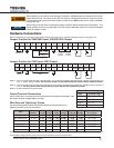
Jumper Position for 208V/240V Input, 240/208/120V Output
Jumper Position for 230V Input, 230V Output
NOTE 1 – If AC input power is 208 Vac rated, short terminals 11 and 12 with the provided jumper wire/bus bar. DO NOT jumper terminal 13 to
12 or 11. Factory Setting is 208Vac. Use the jumper wire/bus strip provided by Toshiba. DO NOT add any additional jumpers.
NOTE 2 – If AC input power is 240 Vac rated, short terminals 12 and 13 with the provided jumper wire/bus bar. DO NOT jumper terminal 11 to
12 or 13. Use the jumper wire/bus strip provided by Toshiba. DO NOT add any additional jumpers.
NOTE 3 – 8-22 kVA UPSs have a jumper bus bar.
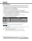
Output Terminal Connections
Connect the load to the output terminals according the load voltage requirements. See
the Output Terminal Voltages table to the right.
Wire Size and Tightening Torque
Use the following table to select the recommended wire size and terminal lug
tightening torque for I/O wire connections.
Item
Terminal
Number
AWG
3.6 kVA
AWG
6 kVA
AWG
8 kVA
AWG
10 kVA
AWG
14-18 kVA
AWG
22 kVA
Tightening Torque
lb.-in. (N•m)
AC Input Lines 1 and 2 12 (8)
10 (8) 8 (1/0) 6 (1/0) 4 (1/0) 1 (1/0)
14.2 (1.56)
AC Output Lines 4, 5, and 7 12 (8)
10 (8) 8 (1/0) 6 (1/0) 4 (1/0) 1 (1/0)
14.2 (1.56)
AC Output Neutral 6 12 (8)
10 (8) 8 (1/0) 6 (1/0) 4 (1/0) 1 (1/0)
14.2 (1.56)
Ground 3 and 8 12 (8)
10 (8) 8 (1/0) 6 (1/0) 4 (1/0) 1 (1/0)
14.2 (1.56)
EPO Switch 14 and 15 16 16 16 16 16 16 9.0 (0.99)
Remote Switch 16 and 17 16 16 16 16 16 16 9.0 (0.99)
Note: Wire size presented as the recommended size followed by a bold number in () that is the maximum wire size the terminal block can
accommodate. See the manual, page 48, for knock-out hole sizes on the back of each model.
3
NOTICE
Output Terminal Voltages
Vout Terminal Lugs
120 V X3 - N, X1 - N
208 V X3 - X2
240 V X3 - X1
230 V X3 - X1
Jumper
position
for 208 V
120 V
208/240 Vin
REMOTE1
208
EPO2EPO1
REMOTE2
COM 240GX3
1
L2 G X1 X2 N
2 3
12 1413 15
8765 114
16 17
L1
120 V
208 V
240 V
Jumper
position
for 240 V
230 Vin
REMOTE1
EPO2EPO1
REMOTE2
GX3
1
L2 (N)
G X1 X2 N
2 3
12 1413 15
8765 114
16 17
L1 (L)
230 V